FENECON Commercial 92 Cluster — Assembly and Operating Instructions
1. Information on these instructions
Personnel must have carefully read and understood these installation and service instructions before starting any work.
1.1. Manufacturer
FENECON GmbH
Gewerbepark 6
94547 Iggensbach
Germany
Phone: +49 (0) 9903 6280 0
Fax: +49 (0) 9903 6280 909
E-mail: service@fenecon.de
Internet: www.fenecon.de
1.2. Formal information on installation and service instructions
© FENECON GmbH, 2026
All rights reserved.
Reprinting, even in part, is only permitted with the permission of FENECON GmbH.
1.3. Version/revision
Version/Revision |
Change |
Date |
Name |
2025.04.01 |
First draft |
04/04/2025 |
FENECON PM |
2025.04.02 |
Completion |
14/04/2025 |
FENECON PM |
2025.8.1 |
Integration split base |
01/08/2025 |
FENECON TK/MR |
2025.11.01 |
Integration of flood warning |
03/11/2025 |
FENECON PM |
1.4. Symbol conventions
|
||
|
||
|
||
|
1.5. Structure of warning notices
If observed, warnings protect against possible personal injury and damage to property. The signal word to classifies the magnitude of danger.
|
Source of the danger
|
Danger sign
The danger sign indicates warnings that warn of personal injury.
Source of danger
The source of danger indicates the cause of the hazard.
Possible consequences of non-compliance
The possible consequences of ignoring the warning are e.g. crushing, burns or other serious injuries.
Measures/prohibitions
Measures/prohibitions include actions that must be taken to avoid a hazard (e.g. stopping the drive) or that are prohibited to avoid a hazard.
1.6. Terms and abbreviations
The following terms and abbreviations are used in the installation and service instructions:
| Term/Abbreviation | Meaning |
|---|---|
AC |
Alternating Current |
BHKW |
Combined heat and power plant (CHP) |
BMS |
Battery Management System |
DC |
Direct Current |
EMS |
Energy Management System |
Energy-Meter |
Electricity meter for the Inverter at the grid connection point |
FEMS |
FENECON Energy Management System |
MPPT |
Maximum Power Point Tracking — Finder for the maximum power point |
GCP |
Grid connection point |
CPC |
Circuit protective conductor |
PV |
Photovoltaic |
RTE |
Round-Trip-Efficiency (RTE) |
SG-Ready |
Smart-Grid-Ready — Preparation of the Heat pump for external control |
SoC |
State of Charge |
SoH |
State of Health — Ageing condition |
VDE |
Verband der Elektrotechnik Elektronik Informationstechnik e. V. |
Widget |
Component of online monitoring |
1.7. Scope of delivery
| Item | Component | Amount | Comment |
|---|---|---|---|
1 |
KACO 92 kW — Inverter |
1 |
|
2 |
FENECON Commercial — BMS box (incl. FENECON Energy Management System) |
1 |
|
3 |
FENECON Commercial — Parallel switch box |
1 |
|
4 |
FENECON Commercial — Extension Box |
1 |
up to 4, depending on the system configuration |
5 |
FENECON BMS box |
1 |
per battery tower |
6 |
FENECON Battery Module |
15 |
per battery tower, depending on the ordered capacity |
7 |
FENECON Base (included with FENECON BMS box) |
1 |
per battery tower |
8 |
KDK 2PU CT |
1 |
| Component | Comment |
|---|---|
Installation and service instructions FENECON Commercial |
Instructions for the installer |
Quick start guide FENECON Commercial |
Quick start guide for the installer |
Operating instructions FENECON Commercial |
Instructions for the user/end customer |
2. Safety
2.1. Intended use
The FENECON electrical energy storage system is used to store electrical energy in rechargeable lithium iron phosphate battery modules (charging) and to provide electrical energy (discharging). This charging and discharging process takes place via a connected inverter. The system must only be used in compliance with the permissible technical data (see section Technical data).
FENECON power storage systems consist of various modules. In particular, these include a BMS (battery management system), the FENECON Energy Management System (FEMS), battery modules and bases. All processes of the electricity storage system are monitored and controlled by the FEMS.
Any other use is not an intended use.
2.2. Reasonably foreseeable misuse
All applications that do not fall within the scope of the intended use are considered misuse.
Work on live parts is generally not permitted. Electrical work must only be carried out by qualified electricians.
The following safety rules must be observed for all work on electrical components:
-
Disconnect.
-
Secure against restarting.
-
Check that there is no voltage.
-
Earth and short-circuit.
-
Cover or shield neighboring live parts.
|
Non-compliance with the safety rules is considered a reasonably foreseeable misuse. |
Other misuses include in particular:
-
improper transportation, installation or assembly at a location, trial operation or operation that could damage the system.
-
change in the specified technical characteristics, including the individual components.
-
change or deviation of the connected load.
-
functional or structural changes.
-
operating the product in a faulty or defective condition.
-
improper repairs.
-
operation without protective devices or with defective protective devices.
-
disregarding the information in the original installation and service instructions.
-
fire, open light and smoking in the vicinity of the storage system.
-
insufficient ventilation at the installation site.
-
unauthorized changes and actions to the electrical energy storage system.
-
use as mobile energy storage.
-
direct use in a PV system (integration via an AC-coupled grid is possible).
2.3. Area of application — Electromagnetic compatibility (EMC)
The low-voltage equipment is intended for use in the following areas of application:
-
General public (public)
Use in other areas of application is not in accordance with the intended use.
2.4. Qualification of the staff
Qualified personnel must be deployed for the intended use, installation and maintenance of the system. The area of responsibility, competence and supervision of the personnel must be precisely regulated by the operator.
2.4.1. Trained electricians
Trained electricians include persons who:
-
are able to carry out work on electrical systems due to their technical training, knowledge and experience as well as knowledge of the relevant standards and regulations.
-
have been commissioned and trained by the operator to carry out work on electrical systems and equipment of the battery system.
-
are familiar with how the battery system works.
-
recognize hazards and prevent them by taking appropriate protective measures.
2.5. General information on the FENECON system
The product must be positioned in such a way that sufficient room for movement can be guaranteed for service and maintenance personnel in every phase of the product’s life. The service life of the product depends on the service life and maintenance intervals carried out by qualified personnel. The service life is particularly influenced by preventive maintenance and servicing.
-
The battery modules must only be installed and the cable connections made by trained electricians.
-
The electrical energy storage system must only be used under the specified charging/discharging conditions (see section Technical data).
-
Keep the electrical energy storage system away from children and animals.
-
Do not connect the plug contacts of the BMS box in reverse.
-
Do not short-circuit battery modules.
-
Only use the battery modules as intended.
-
Improper use can lead to overheating, explosion or fire of the battery modules.
-
-
Read the instructions for installation and operation to avoid damage due to incorrect operation.
-
The battery modules may have insufficient cell voltage after a long storage period. If this is the case, please contact the service department
-
Do not expose the battery modules to high voltages.
-
Place the battery modules on level surfaces.
-
Do not place any objects on the FENECON battery towers.
2.5.1. Environmental influences
-
Keep the electrical energy storage system away from water sources.
-
Do not immerse the electrical energy storage system in water, moisten it or touch it with wet hands.
-
Set up/store the electrical energy storage system in a cool place.
-
Do not heat the electrical energy storage system.
-
Do not expose the electrical energy storage system to open fire.
-
Do not set up or use the electrical energy storage system near open fires, heaters or high-temperature sources.
-
The heat can cause insulation to melt and the safety ventilation to be damaged. This can lead to overheating, explosion or fire on the battery modules.
-
-
No soldering work must be carried out on the electrical energy storage system. Heat introduced during soldering can damage the insulator and the safety venting mechanism and lead to overheating, explosion or fire of the battery modules.
2.5.2. Mechanical influences
-
The battery modules must not be dismantled or modified. The battery modules contain a safety mechanism and a protective device, damage to which can lead to overheating, explosion or fire of the battery modules.
-
Do not step on the electrical energy storage system.
-
Do not attempt to crush or open battery modules.
-
Do not apply any mechanical force to the electrical energy storage system.
-
The battery modules can be damaged and short circuits can occur, which can lead to overheating, explosion or fire of the battery modules.
-
-
Do not throw or drop parts of the power storage system.
-
Do not use defective or dropped battery modules.
-
-
Do not use the electrical energy storage system if changes in color or mechanical damage are detected during assembly, charging, normal operation and/or storage.
-
If the protective devices are damaged, abnormal charging currents and voltages can cause a chemical reaction in the battery modules, which can lead to overheating, explosion or even fire in the battery modules.
2.5.3. Installation, operation and maintenance
|
When carrying out maintenance, servicing and cleaning work, ensure that the product is switched off in a safe manner and secured against being switched on again. In addition, all instructions in these installation and service instructions must be followed. |
Always observe the following safety instructions when installing, operating or maintaining the battery modules:
-
Installation/maintenance work and making cable connections must only be carried out by qualified personnel (trained electricians).
-
During maintenance work, stand on dry insulating objects and do not wear any metal objects (e.g. watches, rings and necklaces) during maintenance work/operation.
-
Use insulated tools and wear personal protective equipment.
-
Do not touch two charged contacts with a potential difference.
-
Measure the battery voltage with a multimeter and ensure that the output voltage is 0 V in off mode.
-
If an anomaly is detected, switch off the battery tower immediately.
-
Only continue the maintenance work after the causes of the anomaly have been eliminated.
-
The battery modules can cause electric shock and burns due to high short-circuit currents.
-
Do not touch the battery module connectors (+) and (-) directly with a wire or metal object (e. g. metal chain, hairpin). Excessive current can be generated in the event of a short circuit, which can lead to overheating, explosion or fire of the battery modules.
2.5.4. Fire protection
-
Do not expose the electrical energy storage system to direct sunlight.
-
Avoid contact with conductive objects (e. g. wires).
-
Keep heat and fire sources, flammable, explosive and chemical materials away from the electrical energy storage system.
-
Explosion hazard: Do not dispose of battery modules in a fire!
2.5.5. Storage
-
Area: Fireproof indoors/outdoors with suitable weather protection.
-
Air temperature: -20 °C to 40 °C.
-
Relative humidity: max. 50 % at +40 °C.
-
Do not store battery modules (lithium iron phosphate batteries) with flammable or toxic objects.
-
Store battery modules with safety defects separately from undamaged battery modules.
|
Storage longer than 12 months
|
2.6. Operating resources
2.6.1. Electrolyte solution of the battery modules
-
Electrolyte solution is used in the battery modules (lithium iron phosphate).
-
The electrolyte solution in the battery modules is a clear liquid and has a characteristic odor of organic solvents.
-
The electrolyte solution is flammable.
-
The electrolyte solution in the battery modules is corrosive.
-
Do not inhale the vapors.
-
If the electrolyte solution is swallowed, induce vomiting.
-
Leave the contaminated area immediately after inhaling the vapors.
-
Eye and skin contact with leaked electrolyte solution must be avoided.
-
Contact with electrolyte solution can cause severe burns to the skin and damage to the eyes.
-
After skin contact: Immediately wash skin thoroughly with neutralizing soap and consult a doctor if skin irritation persists.
-
After eye contact: Immediately flush eye(s) with running water for 15 minutes and seek medical advice.
-
|
Delayed treatment can cause serious damage to health. |
2.7. Residual risk
|
Warning of electrical voltage Work on electrical equipment may only be carried out by qualified electricians from the manufacturer or by specially authorized, trained electricians and in compliance with the safety regulations. |
|
Unknown fault messages Unknown faults and attempts to rectify them can lead to damage to the product. |
|
All doors, emergency exits and areas around the electrical energy storage system must remain clear; do not obstruct escape routes! |
|
The condition of the floor outside the storage system is the responsibility of the user. However, the housing is sealed so that no electrolyte can escape. |
2.8. Behavior in emergency situations
Proceed as follows in emergency situations:
-
Disconnect the electrical energy storage system from the grid.
-
Leave the zone of danger immediately.
-
Secure the area.
-
Inform those responsible.
-
Call a doctor if necessary.
2.9. Pictograms
Pictograms on the system indicate dangers, prohibitions and instructions. Illegible or missing pictograms must be replaced by new ones.
| Pictogram | Meaning | Description |
|---|---|---|

|
Warning of dangerous electrical voltage |
Pictogram on the enclosure, and marking of components which do not clearly indicate that they contain electrical equipment which may be the cause of a risk of electric shock. |

|
General warning sign |
|

|
Battery charging hazard warning |
Pictogram on enclosure and marking of components not clearly identified as containing electrical equipment that may give rise to a battery charging hazard. |

|
No naked flames; fire, naked source of ignition and smoking prohibited |
Pictogram on the enclosure and marking of components that do not clearly indicate that they contain electrical equipment that may present a risk of naked flames, fire, naked sources of ignition and smoking. |

|
Protective earthing symbol |
|

|
Separate collection of electrical and electronic equipment |
|

|
Note instructions |
|

|
Use protective headgear |
|

|
Use protective footwear |
|

|
Use protective gloves |
|

|
CE mark |
|

|
Product is recyclable. |
2.10. Operating materials/equipment
2.10.1. Electrolyte solution of the battery modules
-
Electrolyte solution is used in the battery modules (lithium iron phosphate).
-
The electrolyte solution in the battery modules is a clear liquid and has a characteristic odor of organic solvents.
-
The electrolyte solution is flammable.
-
The electrolyte solution in the battery modules is corrosive.
-
Contact with electrolyte solution can cause severe burns to the skin and damage to the eyes.
-
Do not inhale the vapors.
-
If the electrolyte solution is swallowed, induce vomiting.
-
Leave the contaminated area immediately after inhaling the vapors.
-
Eye and skin contact with leaked electrolyte solution must be avoided.
-
After skin contact: Immediately wash skin thoroughly with neutralizing soap and consult a doctor if skin irritation persists.
-
After eye contact: Immediately flush eye(s) with running water for 15 minutes and seek medical advice.
-
Delayed treatment can cause serious damage to health.
2.10.2. Electrical equipment
-
Work on electrical equipment must only be carried out by qualified electricians.
-
The five safety rules must be observed for all work on electrical components:
-
Disconnect.
-
Secure against restarting.
-
Check that there is no voltage.
-
Earth and short-circuit.
-
Cover or shield neighboring live parts.
-
-
Maintenance work must only be carried out by trained specialist personnel (service personnel).
-
Before starting work, carry out visual checks for insulation and housing damage.
-
The system must never be operated with faulty or non-operational electrical connections.
-
To avoid damage, lay supply lines without crushing and shearing points.
-
Only insulated tools must be used for maintenance on uninsulated conductors and terminals.
-
Control cabinets (e. g. inverter housing) must always be kept locked. Only authorized personnel with appropriate training and safety instructions (e. g. service personnel) should be allowed access.
-
The inspection and maintenance intervals for electrical components specified by the manufacturer must be observed.
-
To avoid damage, lay supply lines without crushing and shearing points
-
If the power supply is disconnected, specially marked external circuits may still be live!
-
Some equipment (e. g. inverters) with an electrical intermediate circuit may still carry dangerous residual voltages for a certain period of time after disconnection. Before starting work on these systems, check that they are de-energized.
2.11. Personal protective equipment
Depending on the work on the system, personal protective equipment must be worn:
-
Protective footwear
-
Protective gloves, cut-resistant if necessary
-
Protective eyewear
-
Protective headgear
2.12. Spare and wear parts
The use of spare and wear parts from third-party manufacturers can lead to risks. Only original parts or spare and wear parts approved by the manufacturer must be used. The instructions for spare parts must be observed. Further information can be found in the wiring diagram.
|
Further information must be requested from the manufacturer. |
2.13. IT security
FENECON systems and their applications communicate and operate without an internet connection. The individual system components (inverters, batteries, etc.) are not directly connected to the internet or accessible from the Internet. Sensitive communications via the internet are processed exclusively via certificate-based TLS encryption.
Access to the programming levels is not barrier-free and is accessible at different levels depending on the qualifications of the operating personnel. Safety-relevant program changes require additional verification.
FENECON processes energy data of European customers exclusively on servers in Germany and these are subject to the data protection regulations applicable in this country.
The software used is checked using automated tools and processes established during development in order to keep it up to date and to rectify security-relevant vulnerabilities at short notice. Updates for FEMS are provided free of charge for life.
3. Technical data
3.1. General information
| Description | Value/dimension | |
|---|---|---|
Installation/ |
IP classification |
IP55 |
Operating altitude above sea level |
≤ 2,000 m |
|
Installation/operating temperature |
-20 °C to +60 °C |
|
Relative humidity (operation/storage) |
0 to 100 % |
|
Battery operating temperature |
-10 °C to +50 °C |
|
Optimal operating temperature of the battery |
15 °C to +30 °C |
|
Cooling |
Temperature-controlled fan |
|
Loudness |
< 60 dB |
|
Certification/guideline |
Overall system |
CE |
Inverter |
VDE 4105:2018-11 |
|
Battery |
UN38.3 |
|
3.2. Technical data — Inverter
| Description | Value/dimension | |
|---|---|---|
Inverter model |
KACO blueplanet gridsave 92.0 TL3-S |
|
AC connection |
Grid connection |
400 V, 3L/PE, 50/60 Hz |
Rated voltage |
400 V |
|
Rated power |
92000 VA |
|
Rated current |
3 x 132.3 A |
|
Efficiency |
Max. Efficiency |
Charging: 98.5 % — Discharging: 98.7 % |
General |
Protection specification |
IP66 |
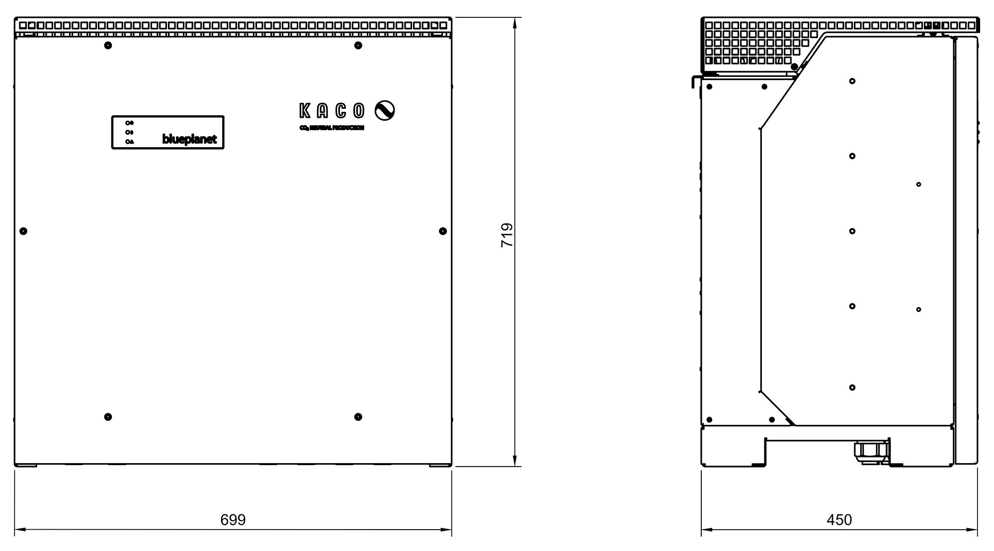
Width | Depth | Height |
699 | 450 | 719 mm |
|
Weight |
80 kg |
|
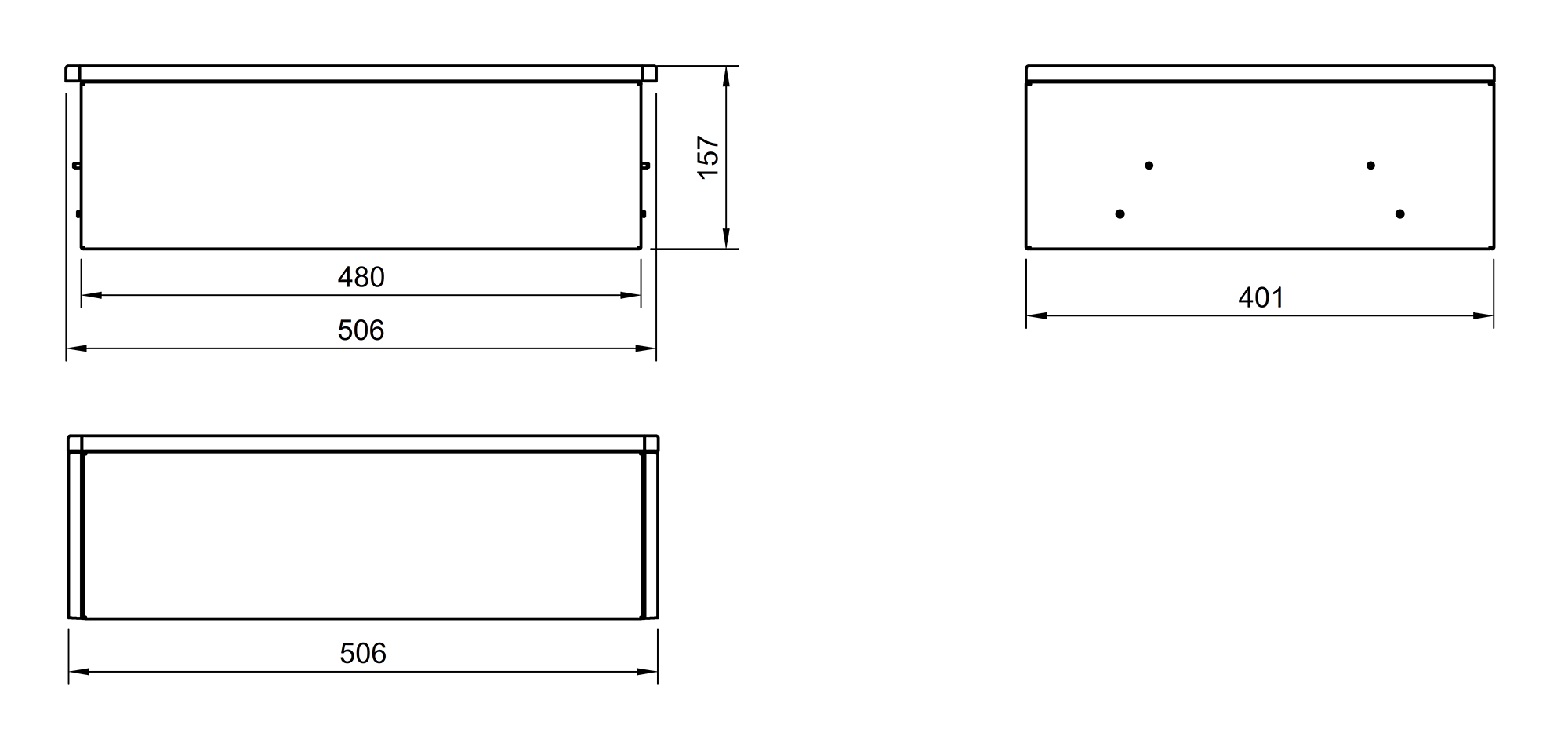
3.3. Technical data — Slave EMS box
| Description | Value/dimension |
|---|---|
Operating voltage DC |
224 V to 672 V |
Max. Current (battery) |
50 A |
Operating temperature |
-10°C to 50°C |
Protection specification |
IP55 (plugged in) |
Input voltage |
100 V to 240 V/1.8 A/50 Hz to 60 Hz |
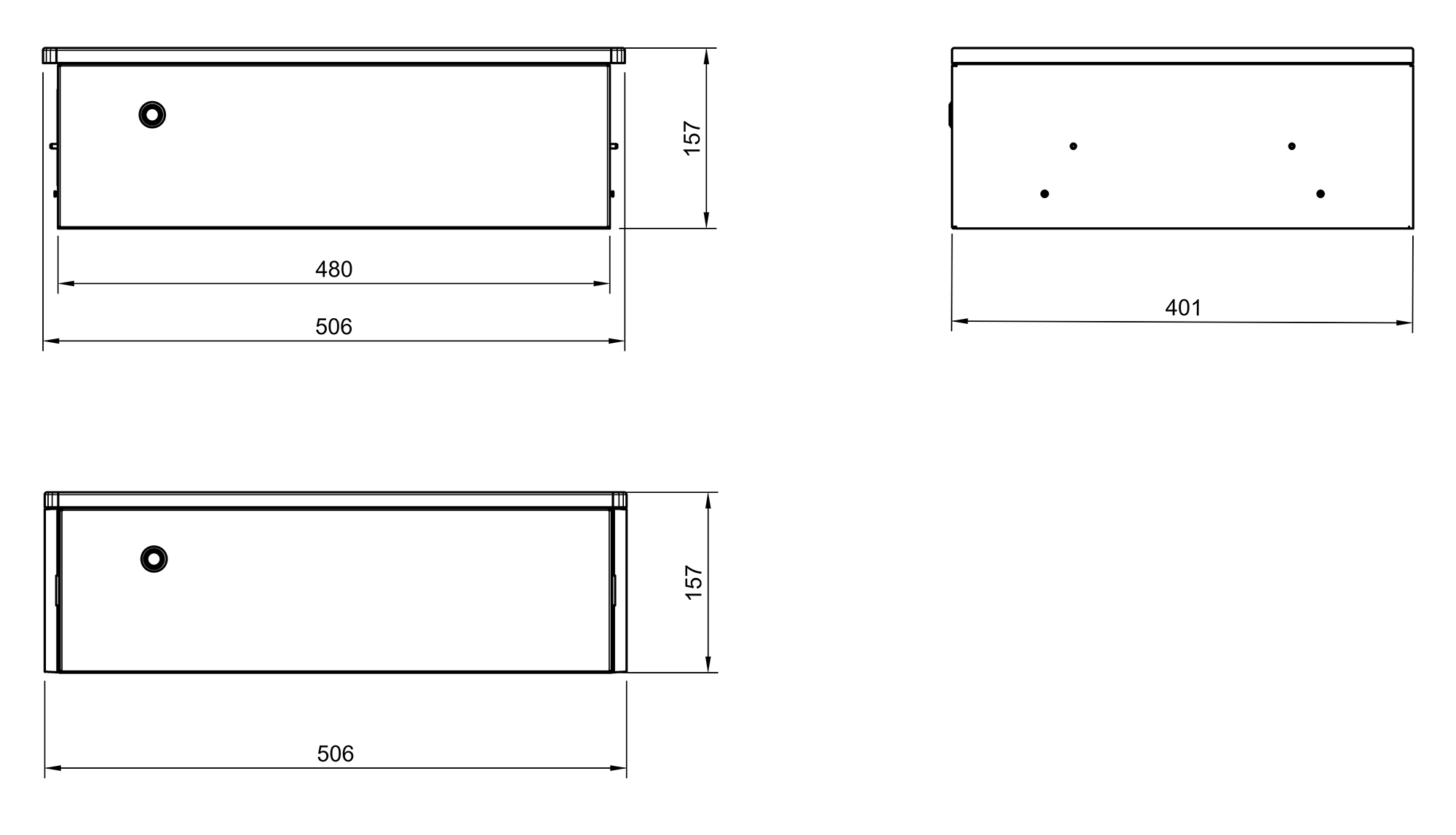
Width | Depth | Height |
506 | 401 | 157 mm |
Weight |
12 kg |
Installation |
stackable |
3.3.1. Dimensions — Slave EMS box
The dimensions are given in mm.
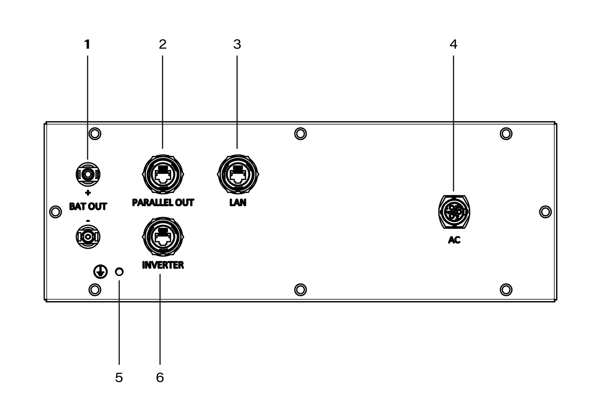
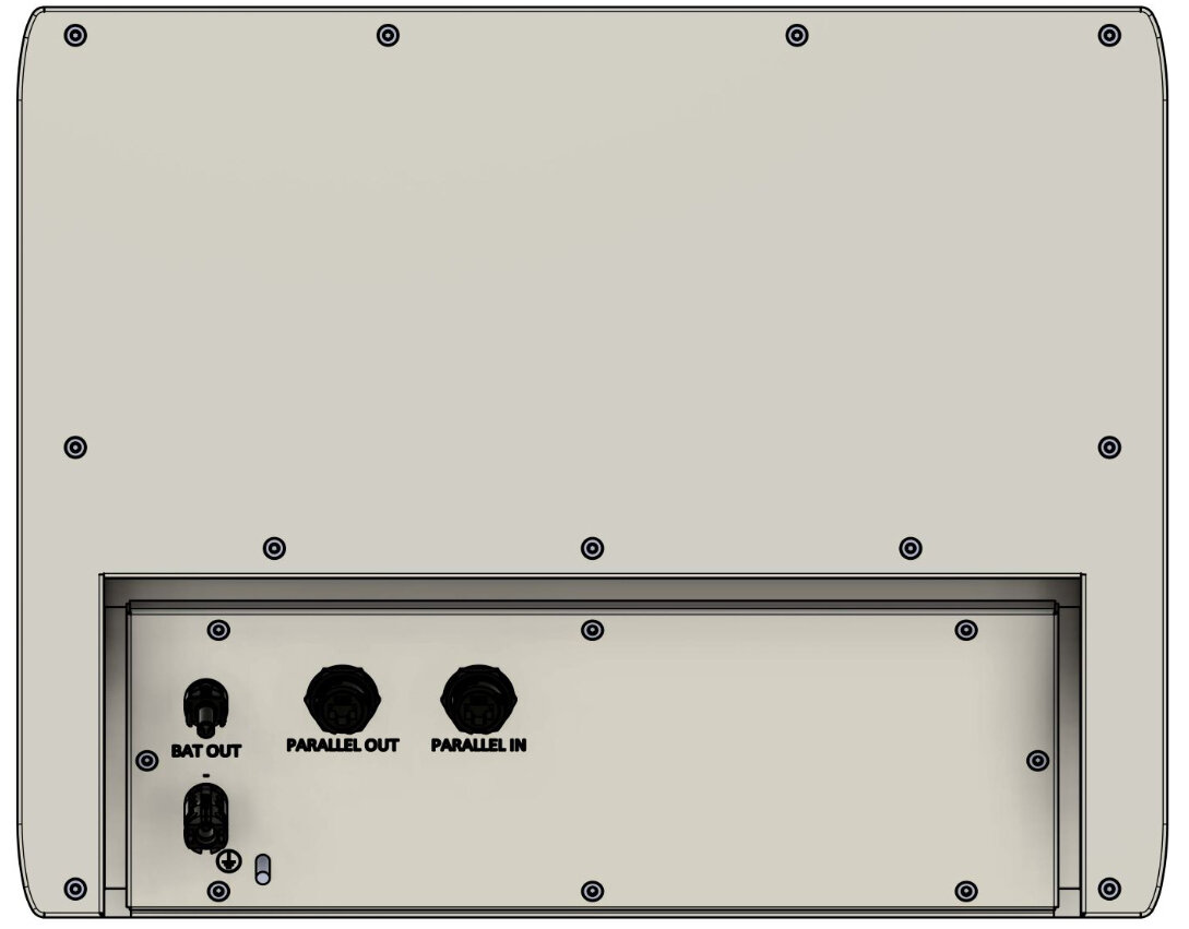
3.3.2. Slave EMS box — Terminal assignment
| List item | Description |
|---|---|
1 |
Battery connection to the inverter (MC4-Evo stor) |
2 |
Communication output for parallel connection of several batteries |
3 |
Connection to Cluster EMS box |
4 |
Power supply to Slave EMS box |
5 |
Earthing connection |
6 |
For future applications (not used) |
3.4. Technical data — Cluster EMS box
| Description | Value/dimension |
|---|---|
Input voltage |
100 V to 240 V | 18 A | 50 to 60 Hz |
Operating temperature |
-20 °C to 40 °C |
Protection specification |
IP55 |
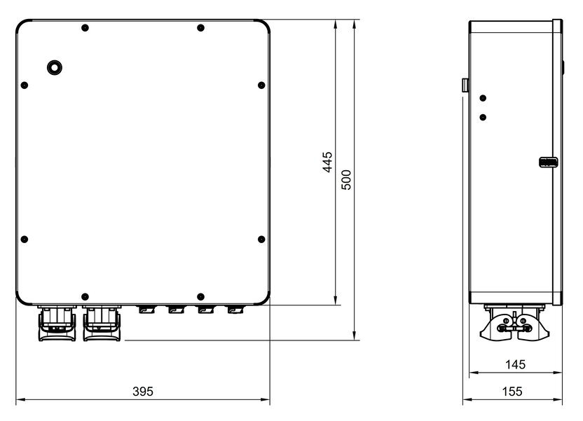
Width | Depth | Height (in mm) |
396 | 155 | 500 |
Weight |
13 kg |
3.4.2. Terminal assignment — Cluster EMS box
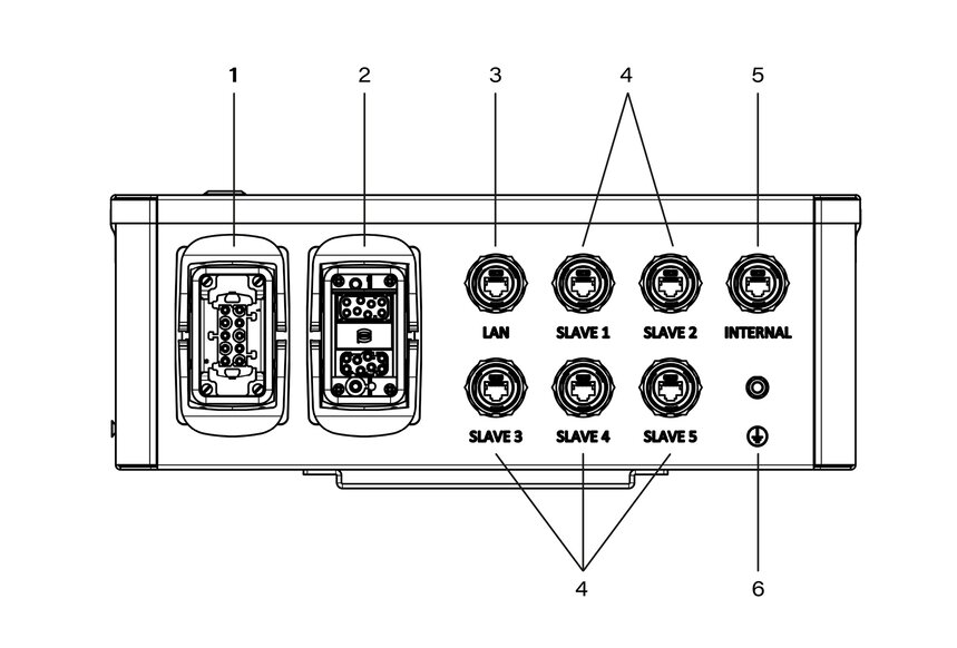
| Item | Description |
|---|---|
1 |
Power supply for Cluster EMS box; potential-free contacts (max. 10 A, measured) (10-pin plug) |
2 |
Communication — RS485, relay outputs; digital inputs (16-pin plug) |
3 |
Connection — Customer network (LAN) RJ45 (network cable not included) |
4 |
Communication — Slave-FEMS |
5 |
For future applications (not used). |
6 |
Earth connection |
3.5. Technical data — Parallel box
| Description | Value/dimension |
|---|---|
Max. operating voltage Operating voltage |
800 V |
Max. Current (inverter) |
150 A |
Max. Current (battery) |
50 A |
Operating temperature |
-20 °C to 40 °C |
Protection specification |
IP55 |
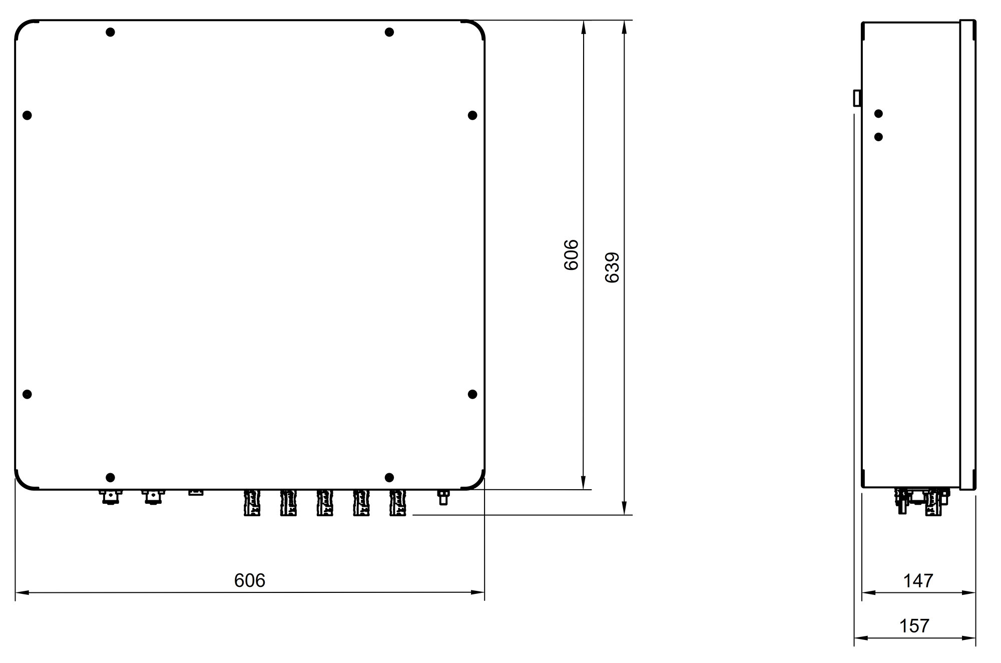
Width | Depth | Height (in mm) |
606 | 157 | 639 |
Weight |
26 kg |

3.6. Technical data — Extension box
| Description | Value/dimension |
|---|---|
DC operating voltage |
224 V to 672 V |
Max. Current (battery) |
50 A |
Operating temperature |
-10 °C ~ 50 °C |
Protection specification |
IP55 (plugged in) |
Width | Depth | Height (in mm) |
506 | 401 | 157 |
Weight |
9 kg |
Installation |
stackable |
3.6.1. Dimensions — Extension box
The dimensions are given in mm.

3.6.2. Extension box — Terminal assignment

| Item | Description |
|---|---|
1 |
Battery connection to the parallel switch box (MC4-Evo stor) |
2 |
Communication output for parallel connection of several battery towers |
3 |
Communication input for parallel connection of several battery towers |
4 |
Earthing connection |
3.7. Technical data — BMS box
| Description | Value/dimension |
|---|---|
Max. operating voltage range |
224 V to 672 V |
Max. input/output current |
50 A |
Optimal operating temperature |
15 to 30 °C |
Operating temperature range |
-20 to 55 °C |
Protection specification |
IP55 (stacked) |
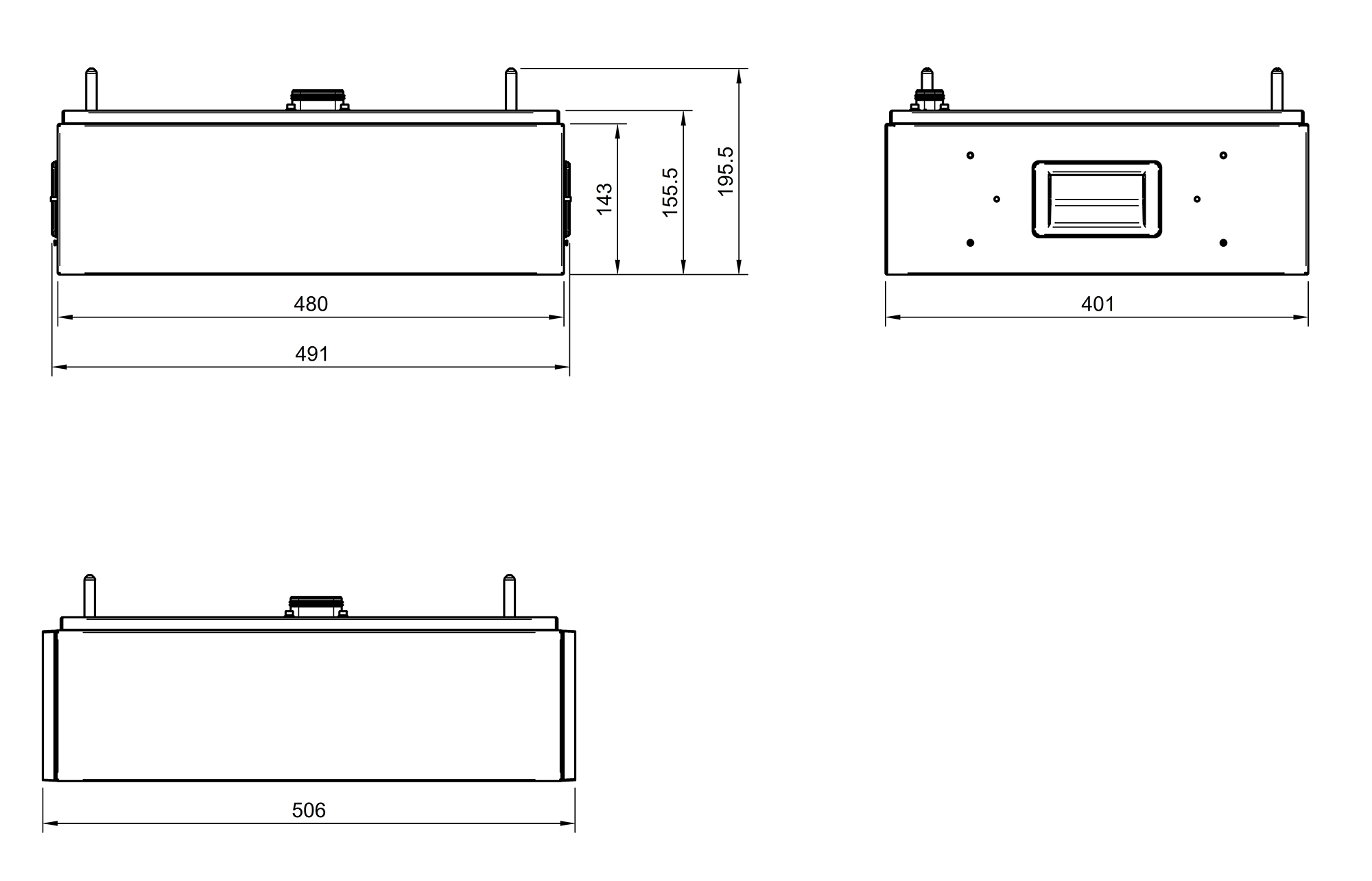
Width (incl. side panel)| Depth | Height |
506 | 401 | 143 mm |
Weight |
13 kg |
Installation |
stackable/wall-mounted |

3.8. Technical data — FENECON battery module
| Designation | Value/dimension |
|---|---|
Usable capacity |
62.4 Ah/2.80 kWh |
Rated voltage |
44.8 V |
Output voltage range |
39.2 V to 50.4 V |
Battery operating temperature range |
-20 °C to +55 °C |
Storage temperature range (over 7 days) |
-30 °C to +60 °C |
Storage temperature range (over 30 days) |
-20 °C to +55 °C |
Storage temperature range (cumulative up to 270 days) |
-10 °C to +45 °C |
Protection specification |
IP55 (plugged in) |
Weight |
30 kg |
Installation |
stackable |
Parallel connection |
4 battery towers in parallel |
Cooling |
natural cooling |
Shipping capacity |
< 30 % SoC |
Module safety certification |
VDE 2510/IEC62619 |
UN transport test standard |
UN38.3 |
Relative humidity during storage |
5 % to 95 % |
|
Storage longer than 12 months
|
3.9. Technical data — Base
| Designation | Value/dimension |
|---|---|
Width (incl. side panel) | Depth | Height |
506 | 401 | 84 mm |
Weight |
6 kg |
Protection specification |
IP55 (plugged in) |
Installation |
stackable |
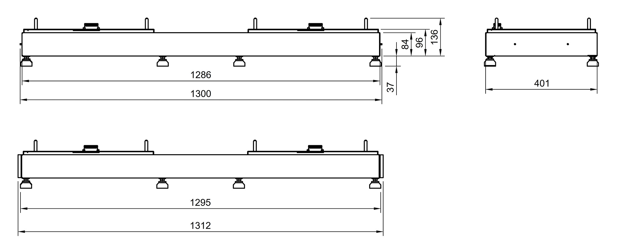
3.10. Technical data — Split base (optional)
| Designation | Value/dimension |
|---|---|
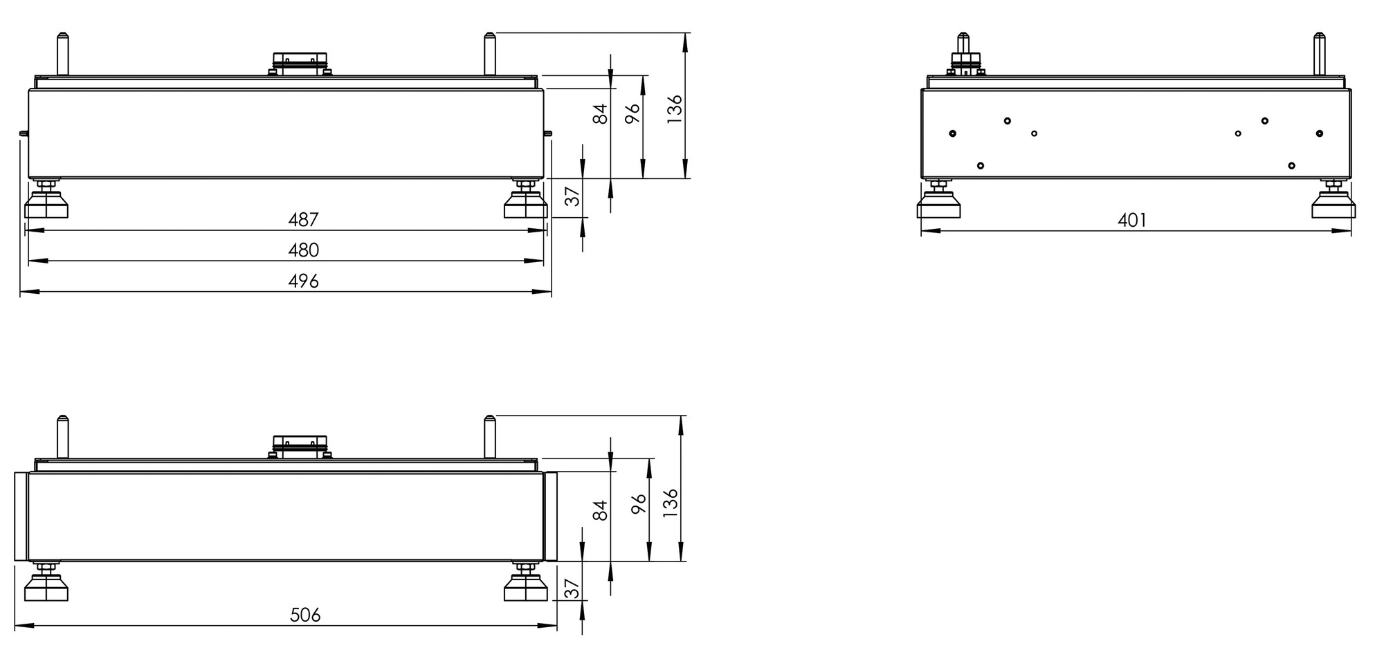
Width (incl. side panel) | Depth | Height |
1312 | 401 | 84 mm |
Weight |
11 kg |
Protection specification |
IP55 (plugged in) |
Installation |
stackable |
4. General description
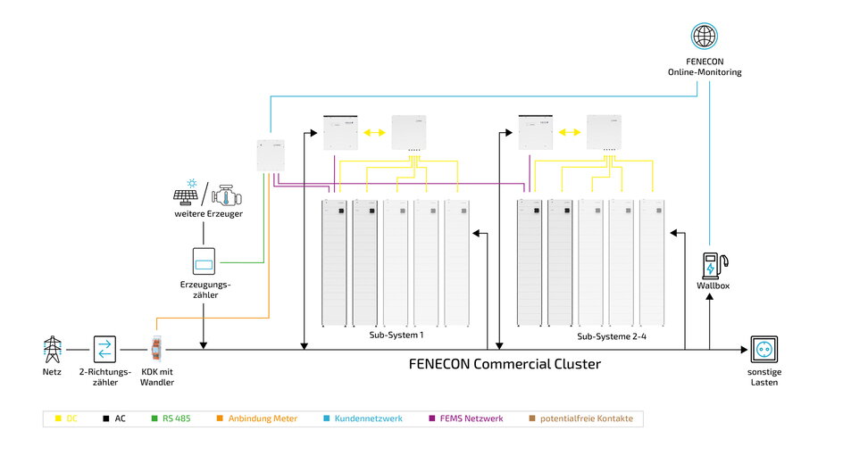
FENECON Commercial 92 Cluster is an AC-coupled electrical energy storage system that can build its own power grid for consumer loads. Lithium iron phosphate batteries (LiFePO4) are used in this modular system for storing electrical energy.
4.1. System configuration — General overview
4.1.1. Structure of an AC sub-system
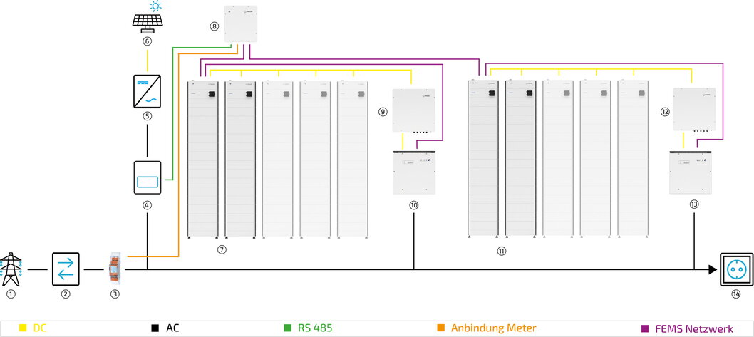
| Item | Description |
|---|---|
1 |
Grid |
2 |
Bi-directional meter |
3 |
Energy meter |
4 |
3-phase sensor or with PV inverter app |
5 |
PV inverter |
6 |
PV system |
7 |
Sub-System 1 |
8 |
Cluster EMS box |
9 |
Parallel switch box for sub-system 1 |
10 |
Inverter for sub-system 1 |
11 |
Subsystems 2-5 |
12 |
Parallel switch box for sub-system 2-5 |
13 |
Inverter for sub-system 2-5 |
14 |
Consumer loads |
4.1.2. Required components
Depending on the system configuration, the following components are required. If up to five battery towers are connected in parallel, make sure that 15 battery modules are installed in each battery tower. In addition, a Cluster EMS box is required for the entire system.
Number of battery towers |
Number of battery modules max. |
BMS box |
Slave EMS box |
Parallel switch box |
Extension box |
2 |
30 |
1 |
1 |
1 |
1 |
3 |
45 |
1 |
1 |
1 |
2 |
4 |
60 |
1 |
1 |
1 |
3 |
5 |
75 |
1 |
1 |
1 |
4 |

5. Assembly preparation
5.1. Scope of delivery
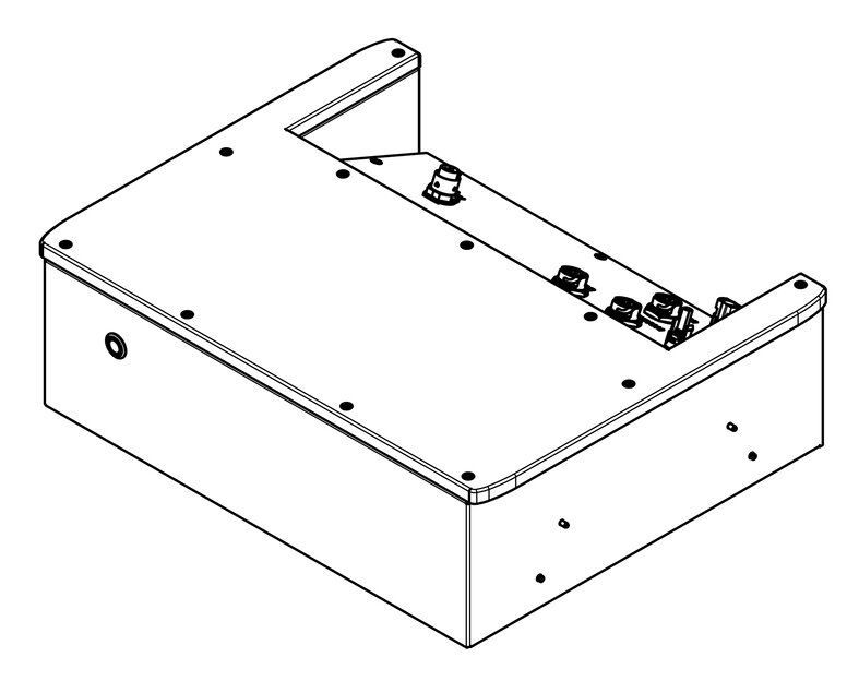
5.1.2. FENECON Commercial 92 — Slave EMS box
| Image | Amount | Description | Item no. |
|---|---|---|---|
|
1 |
Slave EMS box |
FEC011 |

|
2 |
Side panel |
Part of complete set |
|
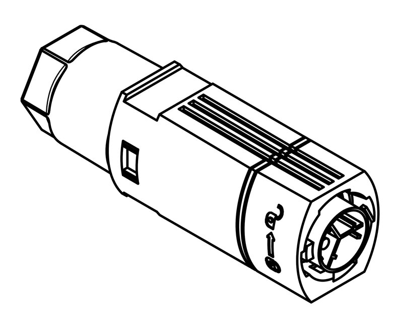
1 |
Phoenix contact plug (power supply) |
|

|
1 |
Jumper plug |
Part of complete set |

|
2 |
Network connector housing |
Part of complete set |

|
2 |
Filler plug, 8 mm |
Part of complete set |

|
1 |
Battery cable set (10 m) |
FEC037 |

|
1 |
Earthing kit |
Part of complete set |

|
1 |
Communication cable Inverter to Slave; 10 m |
Part of complete set |

|
1 |
Installation and service instructions (for installers) |
|

|
1 |
Quick start guide (for installers) |
|
|
|
1 |
Operating instructions (for end customers) |
5.1.3. FENECON Commercial 92 — Cluster EMS box
| Image | Amount | Description | Item no. |
|---|---|---|---|
|
1 |
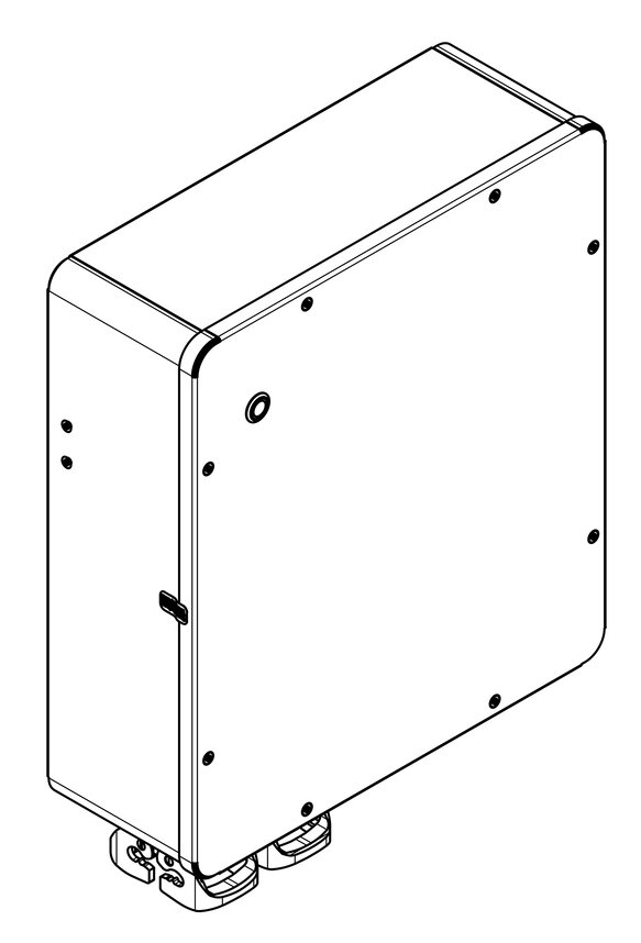
Cluster EMS box |
FEC013 |

|
1 |
Wall bracket — Cluster EMS box |
FEC031 |

|
4 |
Anchor with screw and washer |
Part of complete set |
|
|
7 |
Network connector housing |
Part of complete set |
|
|
9 |
Filler plug 8 mm |
Part of complete set |

|
2 |
Harting housing with cable gland (13-21 mm), multi-hole seal (4 x 8 mm) |
Part of complete set |

|
1 |
Harting socket, 10-pin |
Part of complete set |

|
1 |
Harting insert, 16-pin (assembled) |
Part of complete set |
|
|
1 |
Earthing kit |
Part of complete set |
5.1.4. FENECON Commercial 92 — Parallel switch box
| Image | Amount | Description | Item no. |
|---|---|---|---|

|
1 |
Parallel switch box |
FEC060 in combination |

|
1 |
Wall bracket — parallel switch box |
FEC031 |
|
|
4 |
Anchor with screw and washer |
Part of complete set |

|
1 |
two DC cables, 3 m |
FEC034 |
|
|
1 |
Communication cable; inverter-EMS box; 10 m |
FEC032 |
|
|
1 |
Earthing kit |
Part of complete set |
5.1.5. FENECON Commercial 92 — Extension box
| Image | Amount | Description | Item no. |
|---|---|---|---|

|
1 |
Extension box |
FEC012 |
|
|
2 |
Side panel |
Part of complete set |
|
|
2 |
two DC cables per set, 10 m |
FEC037 |

|
1 |
Communication cable, 2 m |
Part of complete set |
|
|
1 |
Earthing kit |
Part of complete set |
5.1.6. FENECON Commercial 92 — BMS box/base
| Image | Amount | Description | Item no. |
|---|---|---|---|

|
1 |
BMS box |
FEH000 |

|
1 |
Base |
|
|
|
2 |
Side panel (BMS box) |
FEH051 |

|
2 |
Side panel (base) |
|

|
4 |
Wall mounting — Mounting bracket |
Part of connection set |

|
4 |
Wall mounting — Mounting bracket (wall part) |
Part of connection set |

|
4 |
Bolt, M4 x 10 |
Part of connection set |

|
4 |
Bolts for wall fastening, M6 x 12 |
Part of connection set |


5.2. Tools required
The following tools are required for assembly of the system components:
| Image | Description | Image | Description |
|---|---|---|---|

|
Pencil |

|
Spirit level |

|
Impact drill or |

|
Screwdriver set |

|
Meter stick |

|
Side cutter |

|
Allen key, 3 mm |

|
Set of flat spanners |

|
Crimping tool |

|
Multimeter |

|
Pliers for cable glands |

|
Protective eyewear |

|
Safety footwear |

|
Dust mask |

|
Rubber mallet |

|
Vacuum cleaner |

|
Wire stripper |

|
Protective gloves |

|
Torque wrench |

|
Stripping knife |
6. Assembly
The cluster system consists of 2-5 inverters, each connected to 2-5 battery towers. Each sub-system consisting of an inverter and up to five battery towers is set up in the same way, connected to the Cluster EMS box for communication and connected to the customer’s distribution system on the AC side.
The following components must be installed:
-
Inverter
-
Battery tower with base, battery modules, BMS box, and FENECON Commercial 92 EMS box
-
Battery tower with base, battery modules, BMS box and Extension box
-
-
Parallel switch box
-
Cluster EMS box
Before installation, carefully check that the packaging and products are undamaged and that all accessories listed in Chapter 5: [Preparing for installation] are included. If a part is missing or damaged, contact the manufacturer/dealer.
|
The structure of the cluster system is basically equal to the FENECON Commercial 92 system, with the difference that the first battery tower of each slave system has a Commercial Slave EMS box installed, which is then connected to a Cluster EMS box (MASTER). |
6.1. Assembly — Inverter
|
The safety and installation regulations can be found in the inverter manual. |
6.2. Installation — Parallel switch box
6.2.1. Parallel switch box — Safety instructions
|
|
|
|
Suitable protective covers must be fitted! |
-
The parallel switch box must be installed away from direct sunlight, direct rain and snow.
-
The installation room must have permanent ventilation.
-
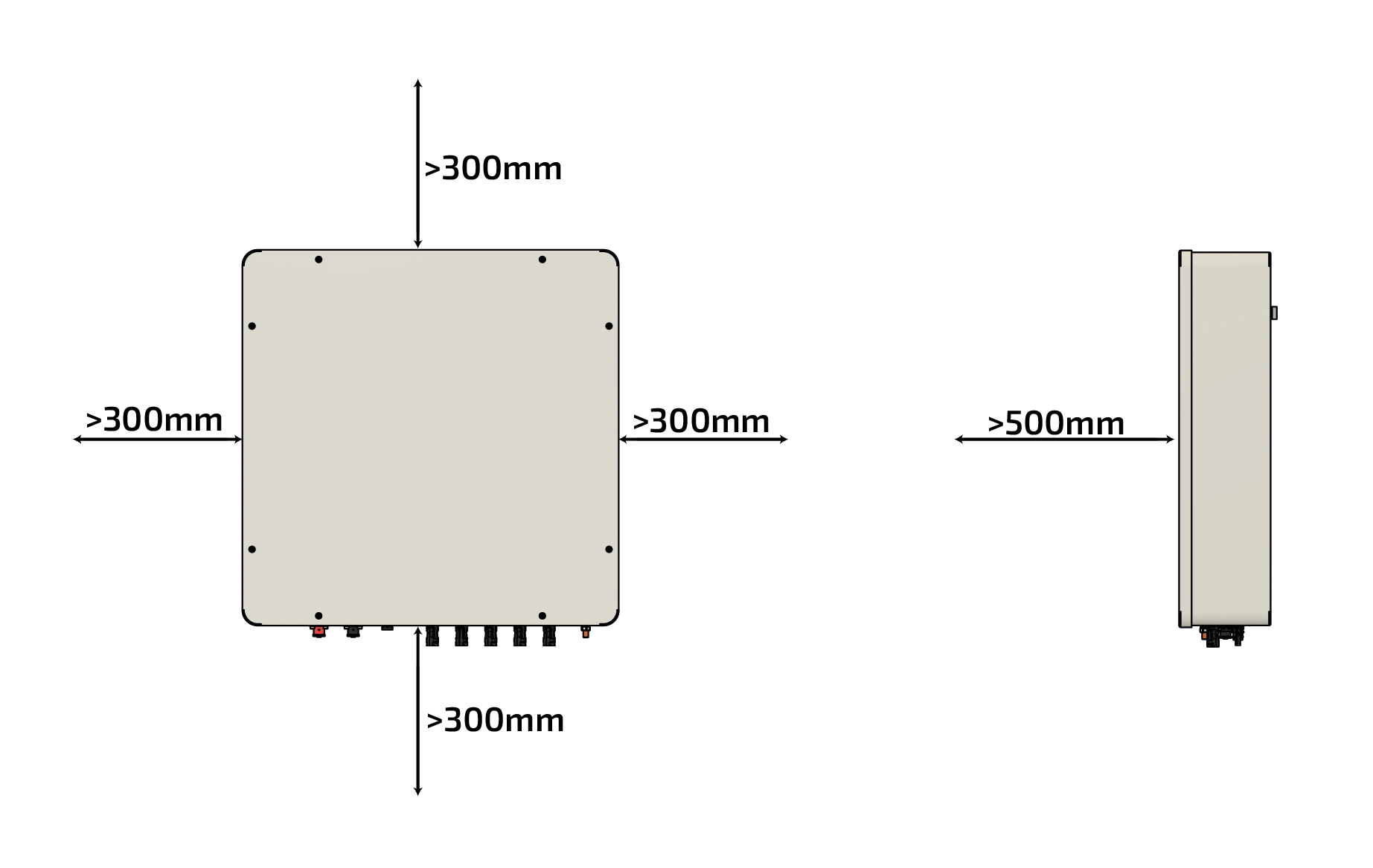
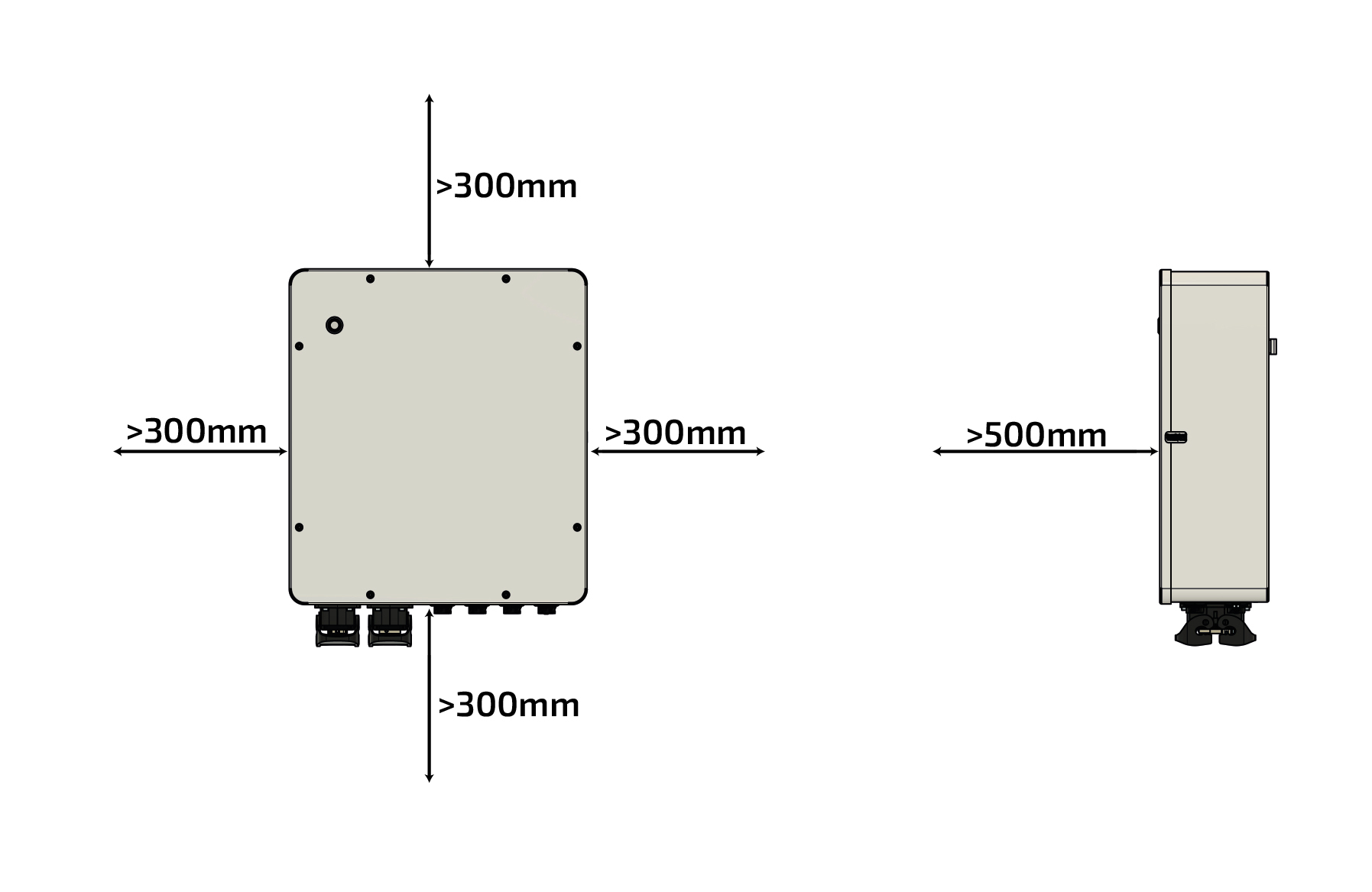
Maintain a clearance of at least 300 mm to the side, above and below the parallel switch box (cable ducts are not included here).
-
Maintain a clearance of at least 500 mm from the front of the parallel switch box.
Proceed as follows to install the parallel switch box on the wall:
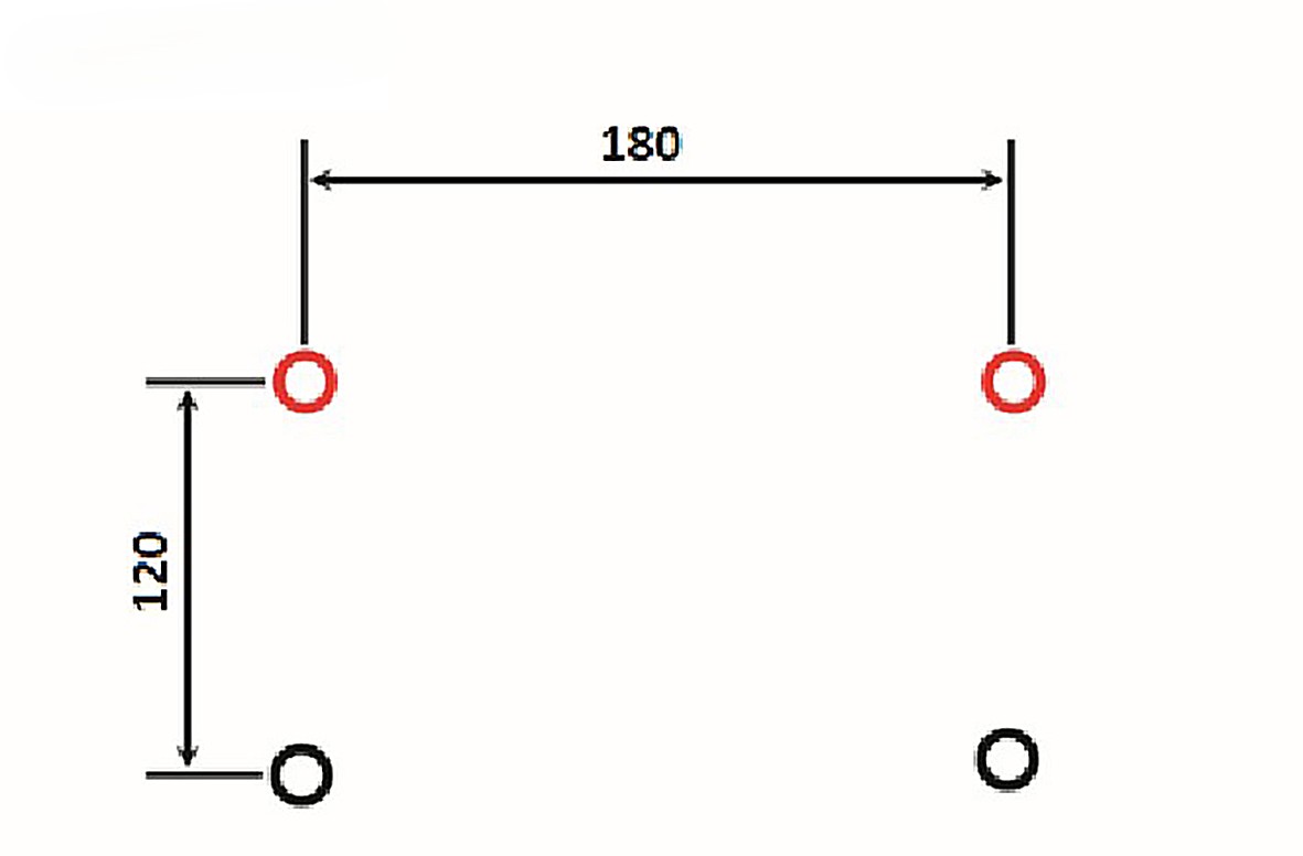
|
|
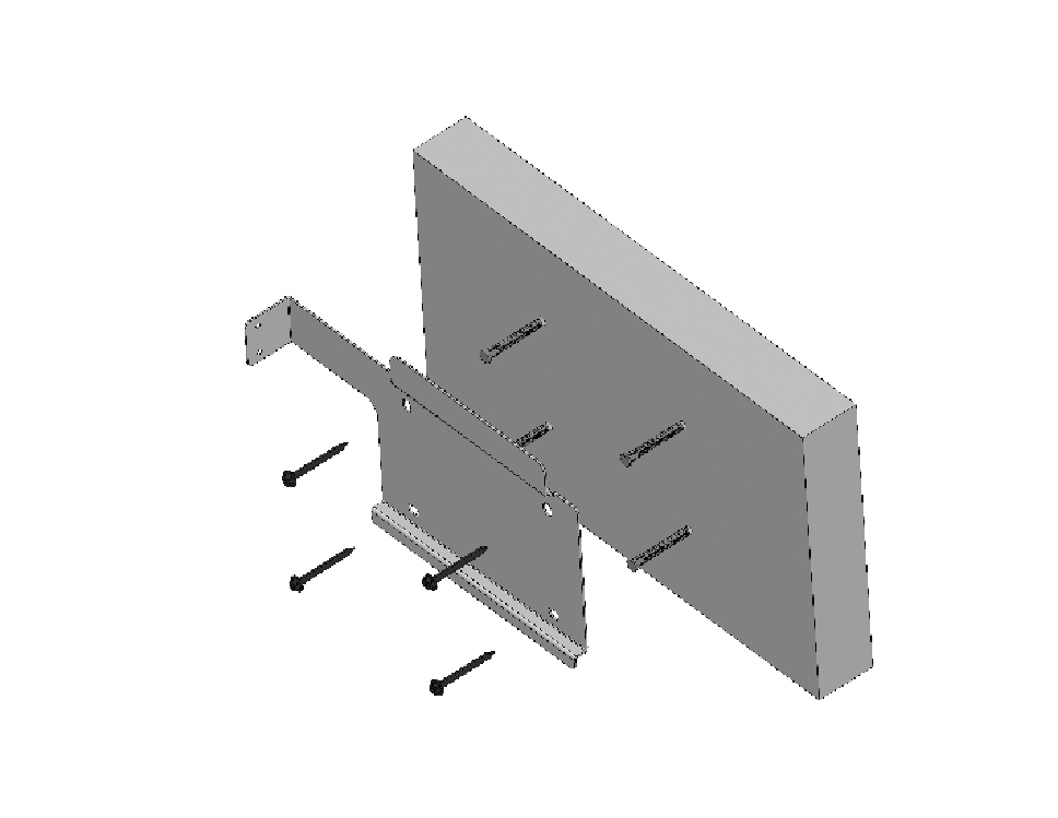
|
|
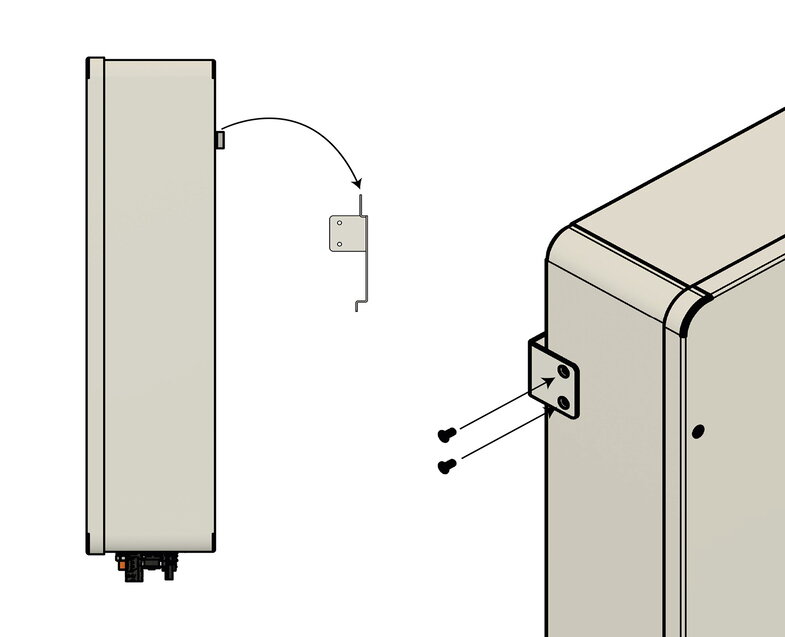
|
|
6.3. Assembly — Cluster EMS box
6.3.1. Cluster EMS box — Safety instructions
|
|
-
The Cluster EMS box must be installed protected from direct sunlight, direct rain and snow.
-
The room where the system is installed must have permanent ventilation.
-
A distance of at least 300 mm must be maintained to the side, above and below the Cluster EMS box (cable ducts are not considered here).
-
Maintain a distance of at least 500 mm from the front of the Cluster EMS box.
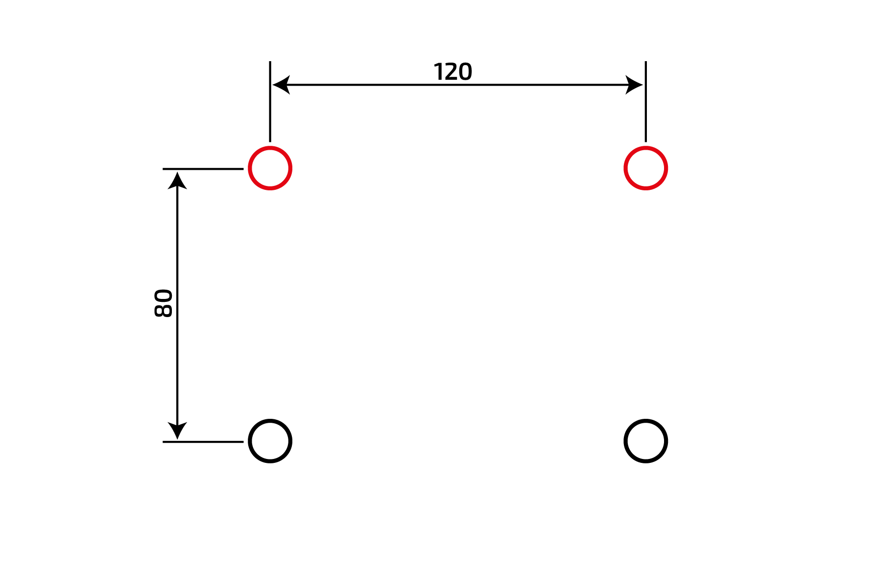
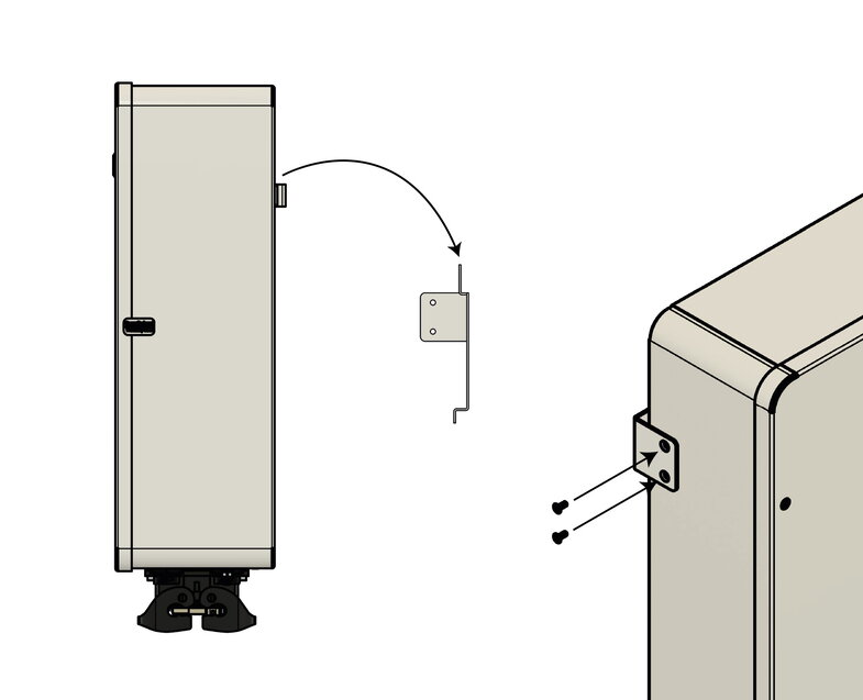
To install the Cluster EMS box on the wall, proceed as follows:
|
|
|
|
|
|
|
6.3.2. Installation conditions and distances — Battery towers
Indoor or outdoor installation
We recommend installing the FENECON Commercial 92 — battery towers in a well-ventilated room without external heat sources. However, the battery towers can also be installed outdoors protected from the weather (e. g. garage).
Installation at 2000 m above sea level and in unventilated locations is not permitted.
Also inadmissible installation sites:
-
those with an explosive atmosphere.
-
Places where flammable or oxidizing substances are stored.
-
Wet rooms.
-
Places where salty moisture, ammonia, corrosive vapors or acid can penetrate the system.
The storage system should also be inaccessible to children and animals.
-
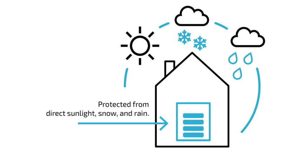
Battery towers must be installed away from direct sunlight and protected from direct rain and snow.
-
In conditions outside the optimum temperature range, the performance of the batteries is reduced. (optimum temperature range: +15 °C to +30 °C)
-
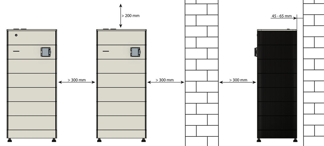
A lateral clearance of 300 mm from a wall and 300 mm between two battery towers is recommended.
-
Clearances of 300 mm from a wall are recommended at the front.
-
A distance of 200 mm from the ceiling is recommended.
|
If the recommended distances are not adhered to, this can make installation more difficult and may result in earlier derating. |
6.4. Assembly — Battery tower
The steps for assembling the battery towers are identical in each case.
6.4.1. Safety instructions
|
Electric shock from live parts
|
|
Electric shock in the absence of overvoltage protection
|
|
Fire and explosion
|
|
Fire and explosion with deeply discharged battery modules
|
|
Toxic substances, gases and dusts
|
|
Arcs due to short-circuit currents
|
|
Destruction of a measuring device due to overvoltage
|
|
Hot surfaces
|
|
Weight of the battery modules
|
|
Sand, dust and moisture
|
|
Electrostatic charging
|
|
Cleaning agents
|
|
Installation site
|
|
Installation
|
Proceed as follows to set up a battery tower:

|
|

|
|

|
|
|
A maximum of 15 battery modules can be stacked on one base. |

|
|
|
Electric shock
|

|
|
6.4.2. Assembly — Slave EMS box and Extension box

|
|

|
|

|
|

|
|

|
|

6.5. Installation — Battery tower on split base
|
The split base can only be used with battery modules with item number FEH021. |
|
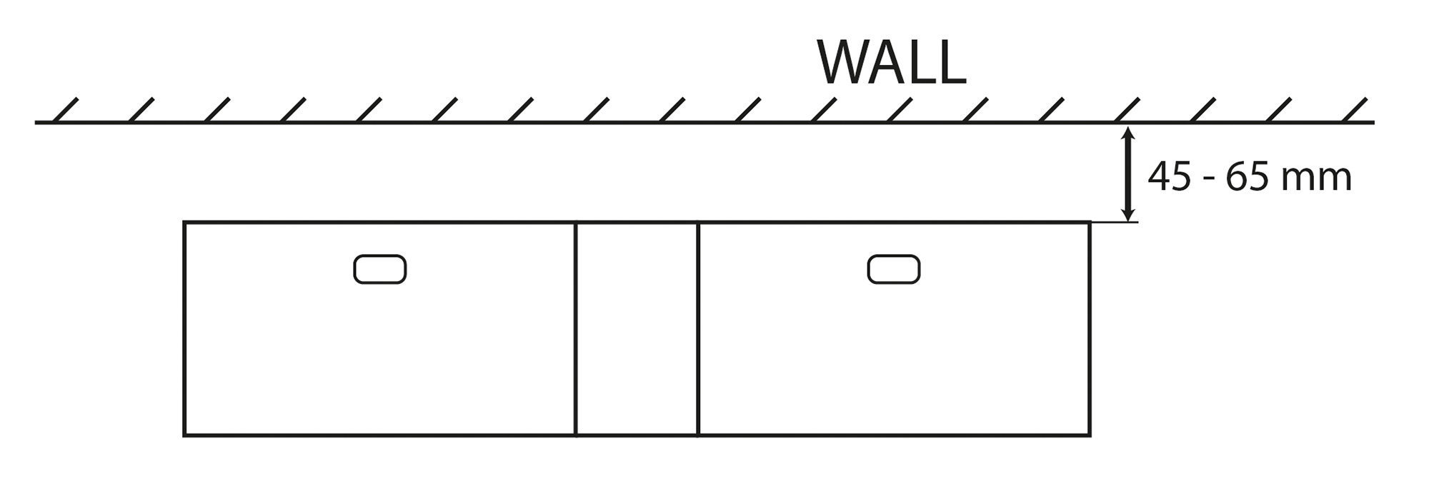
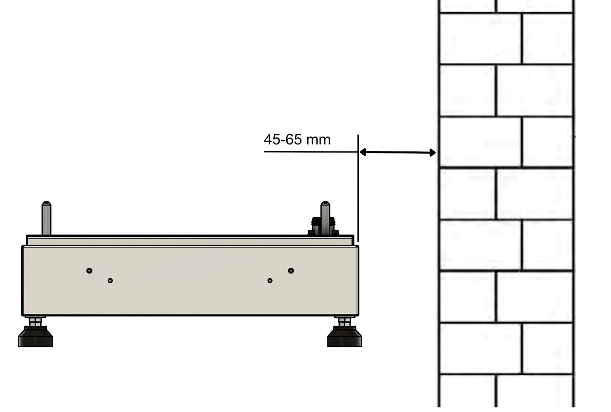
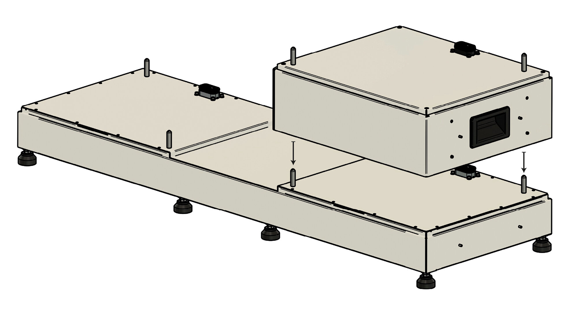
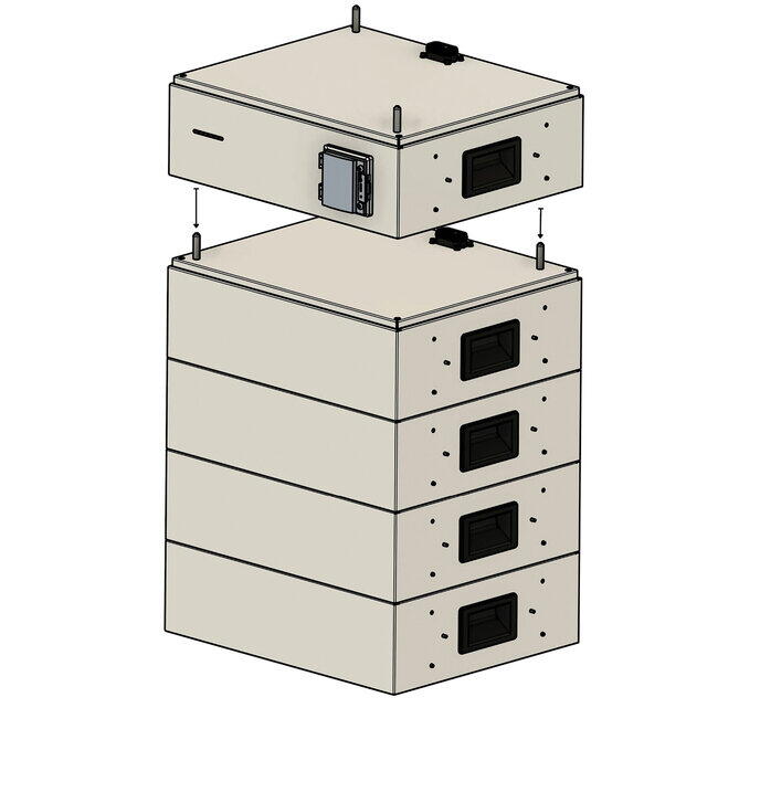
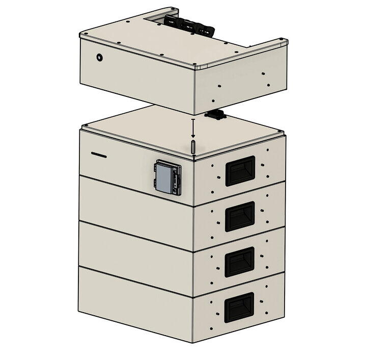
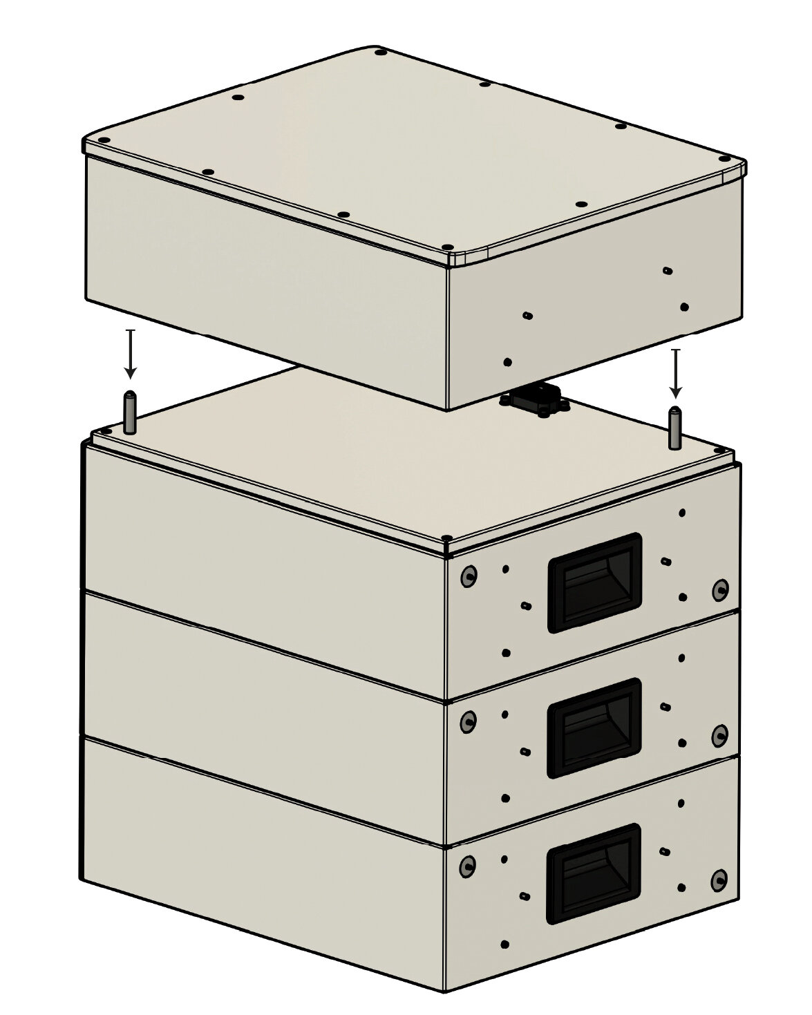
The split base is used for a larger footprint installation of a battery tower, which reduces its height and enables installation in rooms with low ceilings. |
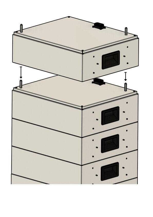
Proceed as follows to set up a battery tower with a split base:
|
|
|
|
|
|
|
|
|
|
Electric shock
|
|
|
||
|
|
||
|
|
||
|
|
||
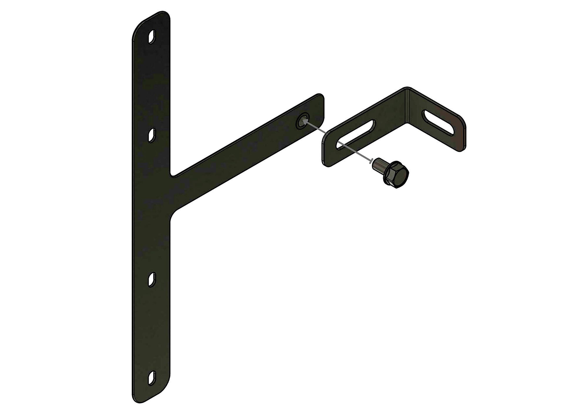
|
|
||
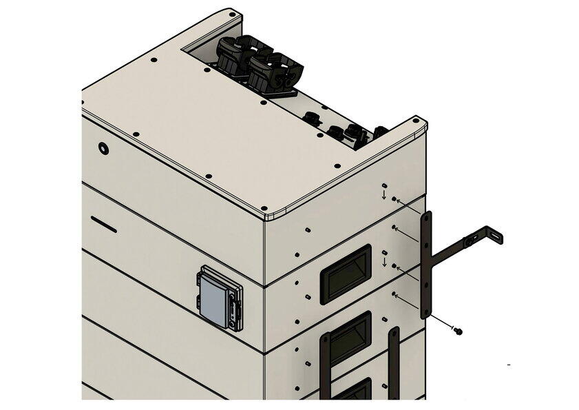
|
|
||
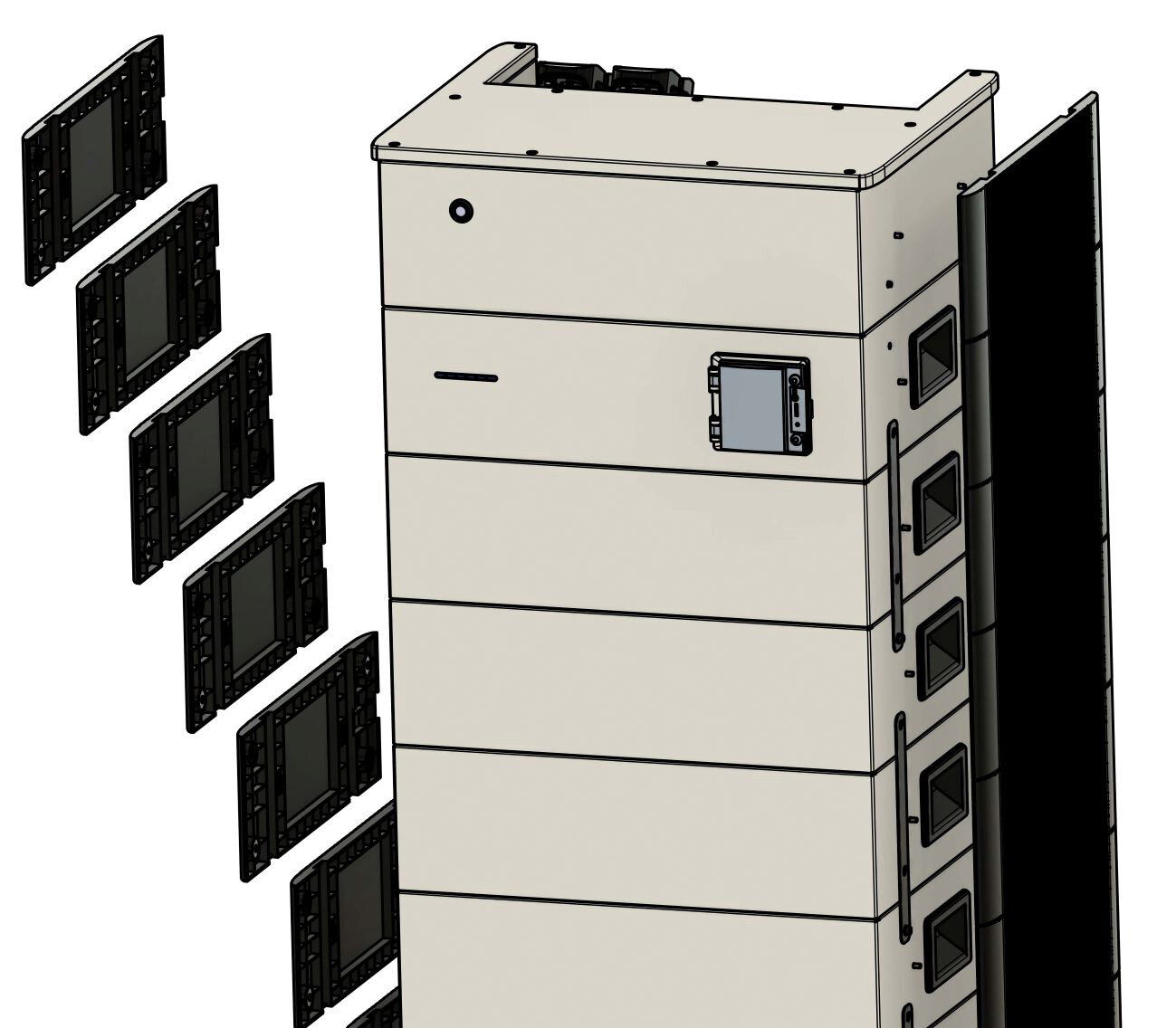
|
|
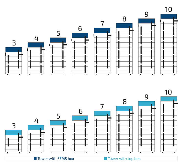
6.6. Electrical installation
6.6.1. Earthing the components
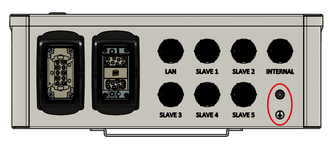
|
Cluster EMS box
|
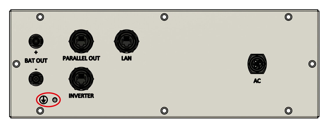
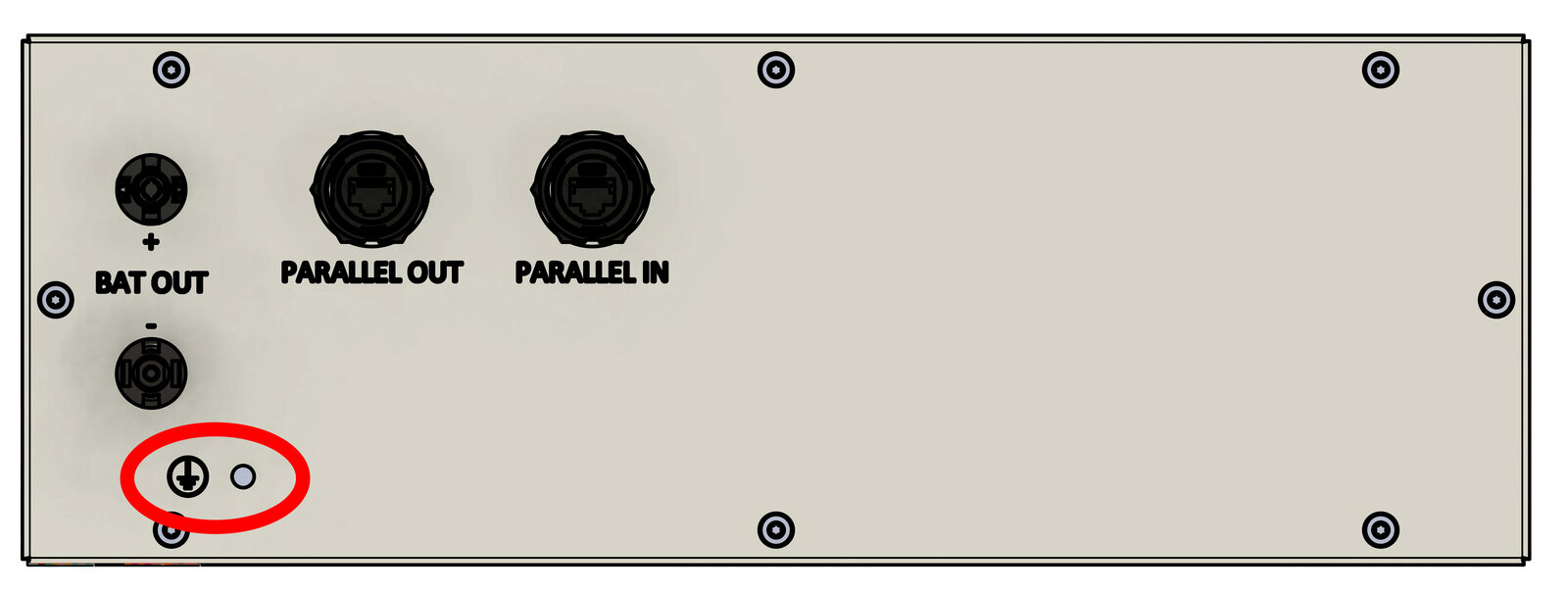
|
Slave EMS and Extension box
|

|
Parallel switch box
|
|
The cross-section of the earthing must be at least 10 mm2. + → The inverter and the battery towers must be earthed individually to the equipotential bonding. |
6.6.2. Connection and wiring of the KACO Inverter

| Item | Description |
|---|---|
1 |
Bi-directional meter provided by the energy supplier |
2 |
Inverter fuse (3-pole). (see inverter manual)1 |
3 |
Fuse for consumer loads with RCD type A and suitable MCBs |
4 |
KACO inverter 92 kW |
5 |
Battery towers |
6 |
Fuse protection maximum C6 or C10 1-pole |
7 |
Consumer loads |
8 |
Grid connection |
9 |
Earth circuit connector |
1 The currently valid national regulations, the specifications of the associated network operator and the manufacturer’s specifications must be observed.
|
The manufacturer’s manual supplied with the inverter must be used for the AC connection of the inverter. |
6.6.3. Connection and wiring of the 3-phase sensor without current transformer
(KDK 2PU CT)
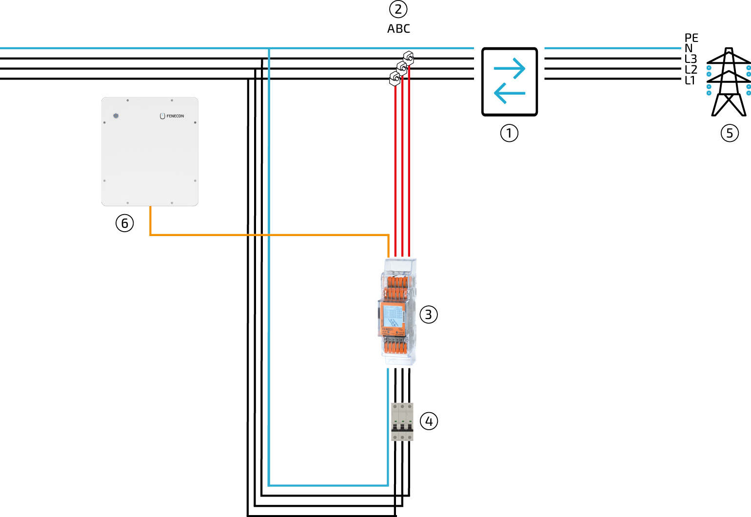
| Item | Description |
|---|---|
1 |
Bi-directional meter from energy supplier |
2 |
Split-core CT (directly behind grid operator meter, not included in standard scope of delivery) |
3 |
Energy meter |
4 |
Fuse for the energy meter (recommended) B6 3-pole |
5 |
Grid |
6 |
Cluster EMS box |
|
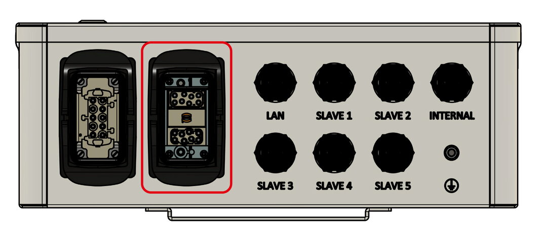
Please note: To install the meter, use the installation and configuration instructions — FEMS package 3-phase sensor without current transformer (KDK 2PU CT): https://docs.fenecon.de/de/fems/fems-app/installationsanleitungen/KDK_2PU_CT_Installationsanleitung.html |
The Modbus communication available with the 2PU CT takes place via a serial RS485 interface (2 or 3 wire), which enables the device to be operated from FEMS. In the standard configuration, 64 devices can be connected to a PC or a controller over 1000 meters with one RS485 interface.
The connections for Modbus communication are located above the meter, in the front row of terminals.

-
COM RS-485 connection from the FEMS direction
-
Data conductor Positive (+) (A conductor)
-
Data conductor Negative (-) (B conductor)
-
Minus (-) contact
-
Plus (+) Contact

|
|

|
|

|
|

|
|
|
|
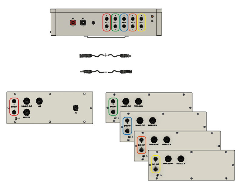
6.6.4. DC cable from the battery towers to the parallel switch box
|
|

|
|
|
The DC plugs used on the battery side are not compatible with standard MC4 plugs. |
6.6.5. Communication between inverter and Slave EMS box

|
|

|
|

|
|

|
|
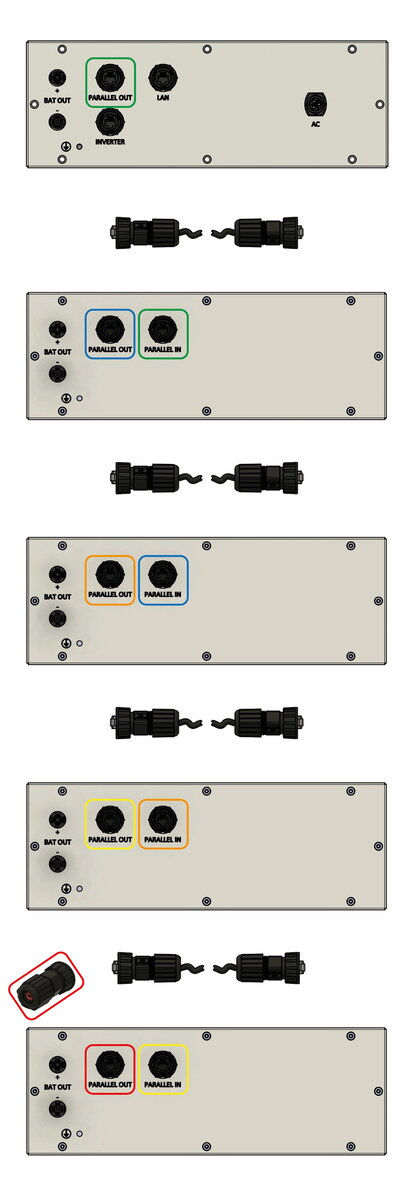
6.6.6. Communication between the batteries
|
|
6.6.7. Communication to the Cluster EMS box
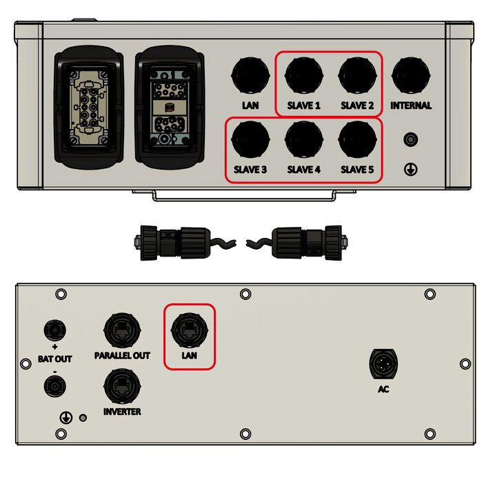
Communication between the individual Slave EMS boxes is not established via the customer network; instead, the up to five inverters are connected to the Cluster EMS box.

|
|
|
If the battery tower is installed indoors, this step can be skipped. And the network cable can be plugged in directly. |

|
|
|
|
|
The system does offer WiFi functionality. |
6.6.8. Communication with the customer network
|
|
|
|
If the battery tower is installed indoors, this step can be skipped. And the network cable can be plugged in directly. |
|
|
|
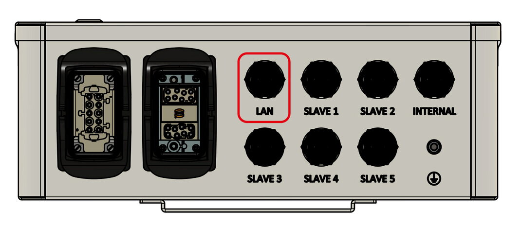
|
|
|
The system does offer WiFi functionality. |
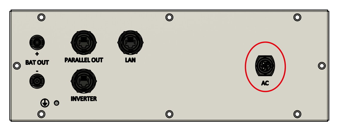
6.6.9. AC connection of the FENECON Slave EMS box
-
An external 230-V-power-supply is required to supply the FENECON EMS box.
-
The purpose of this is to avoid straining the empty battery with additional consumer loads. This can occur particularly in winter when there is no sunshine or when there is snow on the PV system.

|
|
|
|
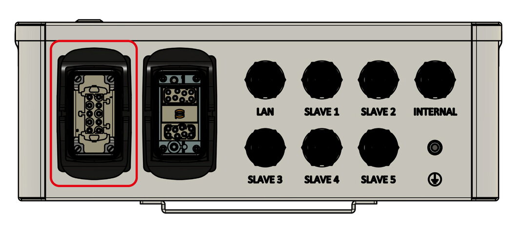
6.6.10. AC connection of the FENECON Cluster EMS box

|
|

|
|

|
|

|
|
|
|
7. Capacity expansion of the system
The capacity can also be expanded at a later date; there is no time limit here.
The maximum capacity is not reached with additional new battery modules, as new modules are equal to the old modules.
7.1. Capacity expansion of the battery tower
by one or more battery modules
If the electrical energy storage system is expanded with additional battery modules after commissioning, proceed as follows:
|
After a capacity expansion, the commissioning wizard must be carried out again. |

|
|
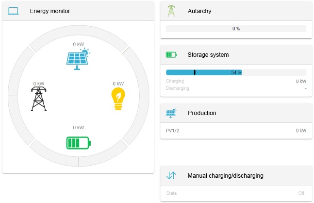
|
|
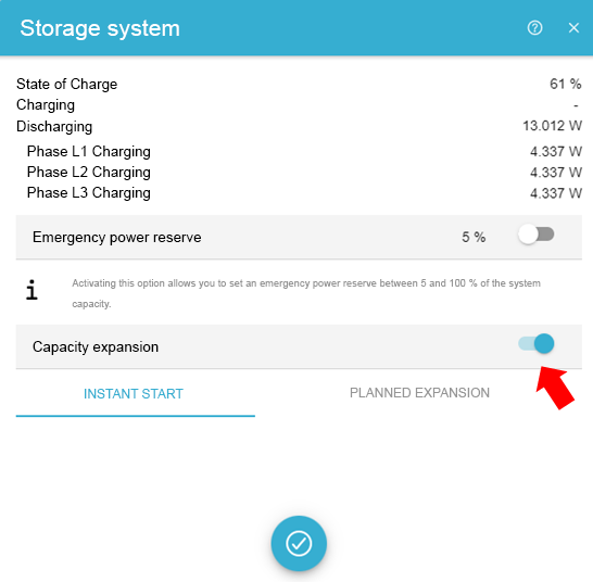
|
|
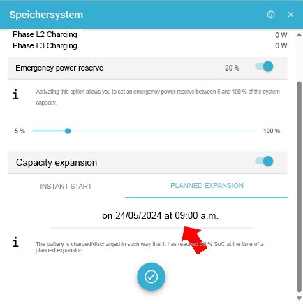
|
|
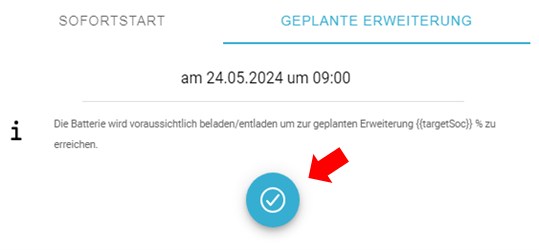
|
|
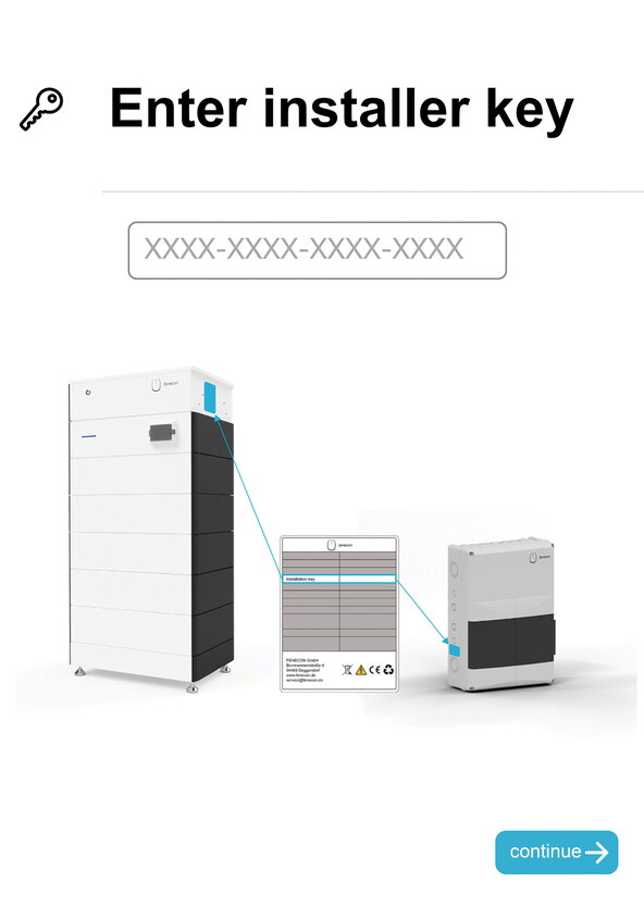
|
|
The capacity can also be extended at a later date; there is no time limit here. You will not reach the full capacity with the new battery module, as the new module will equalize with the old modules.
If the battery tower is extended by additional battery modules after several weeks or months, the following procedure must be followed:
29-30 % SoC |
|

|
|

|
|

|
|

|
|
|
|
|
|
7.2. Capacity expansion of the system
by one or more battery towers
The capacity of the system can be subsequently expanded by one or more battery towers with the same capacity. There is no time limit here.
The full capacity is not achieved with new battery modules, as the new modules become similar to the old modules.
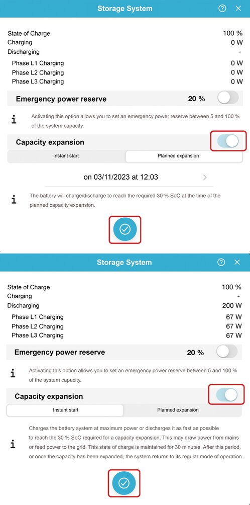
Proceed as follows before the extension:
|
|

|
|

|
|
|
|
|
|
8. FEMS extensions
For the following FEMS extensions, the integrated relays can be used directly on the (first) battery tower.
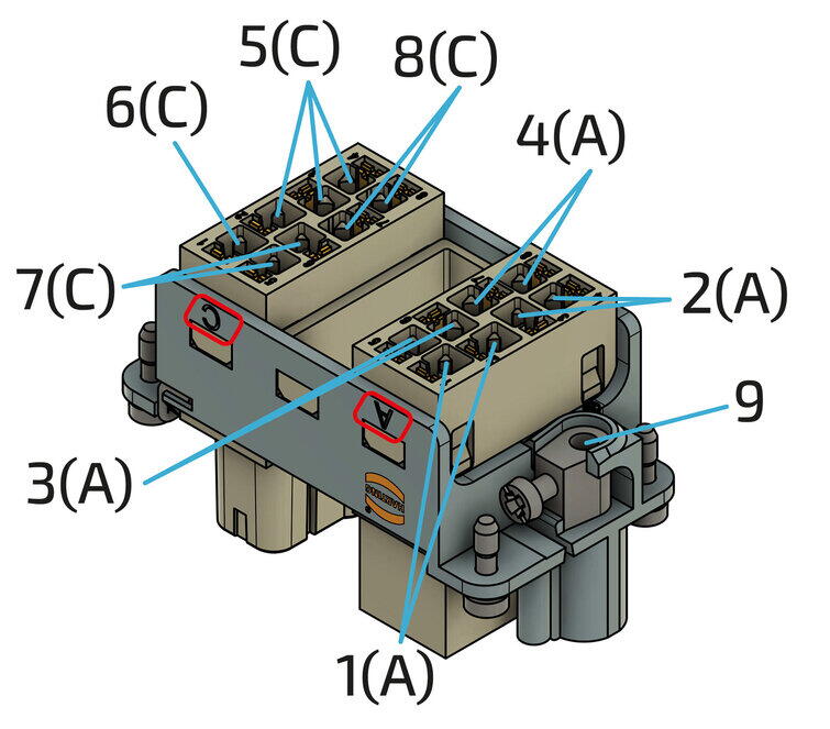
Various pins on the Harting plugs are provided for this purpose.
-
Harting plug 10-pin: 3 x free relay channels (max.: 230 V; 10 A)
-
Harting plug 16-pin: 2 x control contacts (max.: 24 V; 1 A)
-
3 x digital input
-
1 x digital input for § 14a
-
1 x analog output (0-10 V)
-
It may not be possible to connect and operate all apps at the same time.
For more information on the following apps, please visit our homepage.

|
If the integrated relays are not sufficient, an external 8-channel relay board can be connected via Ethernet. |

|
The pin assignment of the Harting plug (10-pin) is shown in detail below. |
| Item | Description |
|---|---|
1 |
230 V supply for internal components |
2 |
Relay 1 (230 V; 10 A) |
3 |
Relay 2 (230 V; 10 A) |
4 |
Relay 3 (230 V; 10 A) |
5 |
Neutral conductor connection (required for integrated meter) |
6 |
PE connection |
|
The pin assignment of the Harting plug (16-pin) is shown in detail below. |
| Item | Description |
|---|---|
1 |
RS485 connection — Inverter |
2 |
RS485 connection — External devices |
3 |
Analog output (0 to 10 V) |
4 |
12 V DC (12 V; GND) |
5 |
3 x digital inputs |
6 |
Digital input for § 14a |
7 |
Relay 5 (24 V; 1 A) |
8 |
Relay 6 (24 V; 1 A) |
9 |
PE connection |
8.1. Connection of a heat pump via "SG-Ready"
The integration of an "SG-Ready" (Smart Grid-ready) heat pump is an advanced form of sector coupling of electricity and heat - often also referred to as a "power-to-heat" application. The control system ensures that the heat pump slightly overheats the thermal energy storage system at times when cheap (solar) electricity is available in order to save electrical energy at times when there is no cheap surplus electricity.

|
|
|
After installing the components, the app still needs to be installed. |
8.2. Connection of a heating element with a maximum of 6 kW
The integration of an electric heating element is the simplest and cheapest form of sector coupling of electricity and heat — often also called a "power-to-heat" application.
If the capacity of the electrical energy storage system is exhausted, self-generated energy must be fed into the public grid with low remuneration. In these cases, it often makes sense to use the surplus current for water heating (e. g. for hot water buffer tanks, pool heating, etc.). This way, other energy sources (e. g. wood or oil) can be saved.

|
|
|
Ensure that three different phases are used. If only one phase is used, damage may occur. |
|
After installing the components, the app still needs to be installed. |
| Manual mode is only suitable for temporary operation. For permanent operation, the external relay control must be used. |
8.3. Control of a heating element greater than 6 kW
(control via external relay)
| The externally installed relays must be laid out according to the power of the installed heating element. |

|
|

|
|

|
|
|
After installing the components, the app still needs to be installed. |
8.4. Controlling a CHP unit
The integration of a combined heat and power plant (CHP) into electrical energy management is an advanced form of sector coupling of electricity and heat.
This allows using the CHP as an electrical generator that is independent of the time of day and weather conditions. When the state of charge of the electrical energy storage system is low, the CHP is given a switch-on signal to produce electricity. This is useful, for example, if the battery capacity is not sufficient to cover electricity consumption at night. This avoids the need to purchase expensive current from the grid.
When the battery is charging, this signal is stopped again to prevent the CHP’s current from being fed into the grid unnecessarily.
|
|
|
|
After installing the components, the app still needs to be installed. |
8.5. Additional AC meter
-
If additional meters have been installed for monitoring other consumer loads or generators, these must be integrated into the circuit in accordance with the manufacturer’s instructions.
-
The communicative integration is shown below using a 3-phase sensor without a current transformer as an example.
-
Only meters approved by FENECON can be integrated.
-
The first production meter is always integrated with Modbus ID 6. All others in ascending order. The baud rate is 9600.

|
|

|
For example SOCOMEC E24
|

|
For example KDK 4PU
|
|
If several meters are to be installed, they can be connected in series for communication purposes. For this purpose, the first meter can be bridged to the second, etc. The Modbus address must be set in ascending order. |
|
Once the components have been installed, the app still needs to be installed.
|
8.6. Activation of the app in the FEMS App Center
After installing the hardware FEMS App extension, it still needs to be activated in the App Center. To do this, proceed as follows:

|
|
|
|
| First check whether updates are available for the FEMS. |
9. Updating the FEMS
To be able to use all FEMS Apps extensively and in the latest version, carry out a system update to the latest version.
-
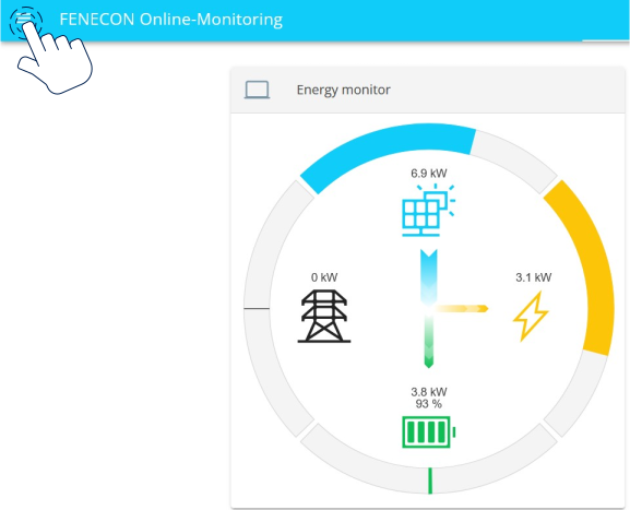
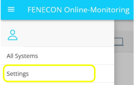
Open the burger menu at the top left of FENECON Online Monitoring.
-
Select Settings.
-
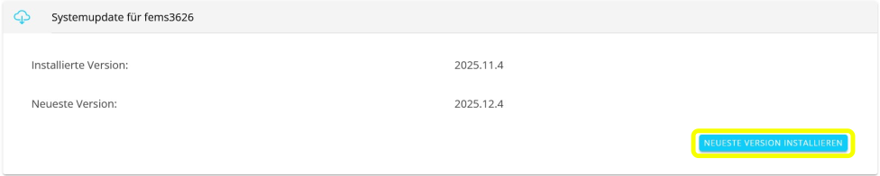
Select FEMS System.

-
Click on INSTALL LATEST VERSION to update the system. If the latest version is already installed, you do not need to do anything else.
|
To return to the settings menu after the FEMS system update: Click on the arrow at the top left. This applies to all submenus in the Settings area. |

10. Starting point: FEMS App Center
-
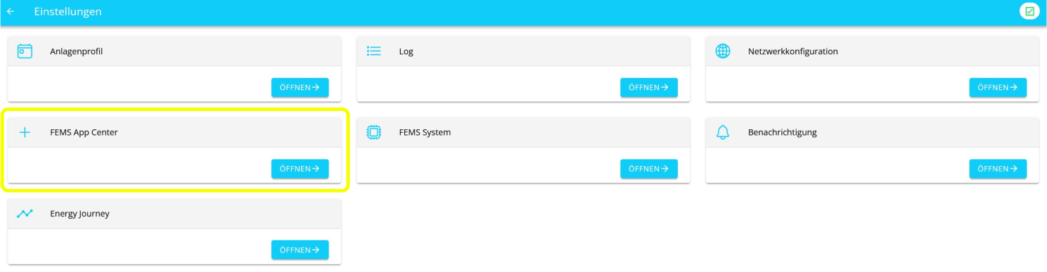
After you have performed a system update, open the FEMS App Center.
-
Alternatively, go to the FEMS App Center via the top left burger menu in the FENECON Monitoring.
-
-
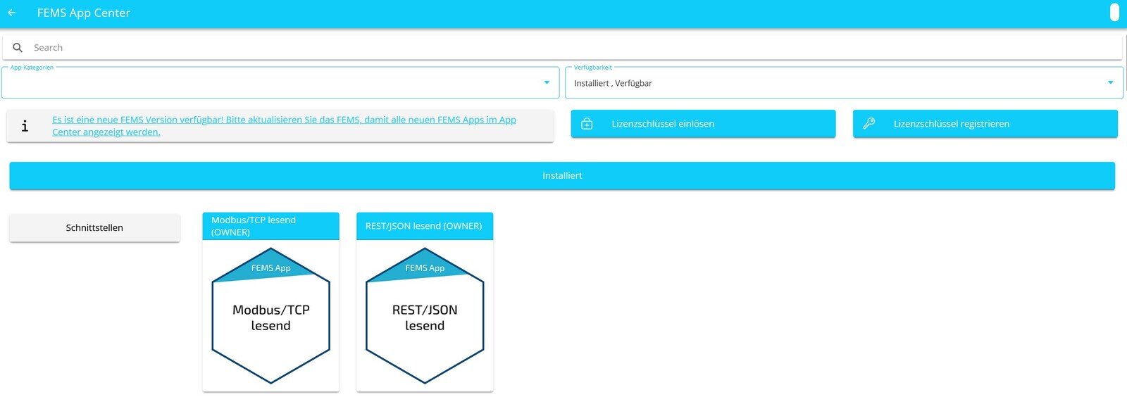
You are now in the App Center. From here you can redeem and register licence keys for apps, install new apps and edit or subsequently configure apps that are already installed.
10.1. Installation of further FEMS Apps
The following instructions show an example of how to install an FEMS App PV inverter.
There are two ways to install an FEMS App via the App Center.
10.1.1. Installation after redeeming a licence key
After a licence key has been redeemed, a selection of available apps that can be installed is displayed.
The App Center offers a search bar and a filter option to get to the desired app more quickly:
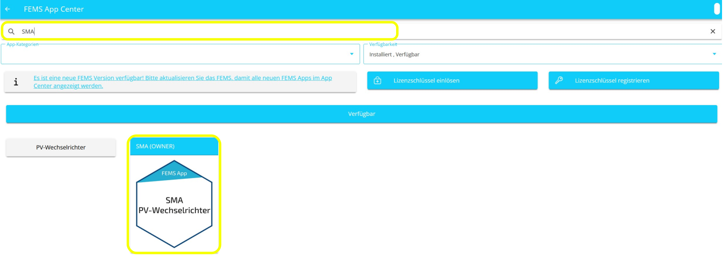
In the example, the FEMS App SMA PV Inverter was searched for. This app is selected by clicking or tapping on the tile.
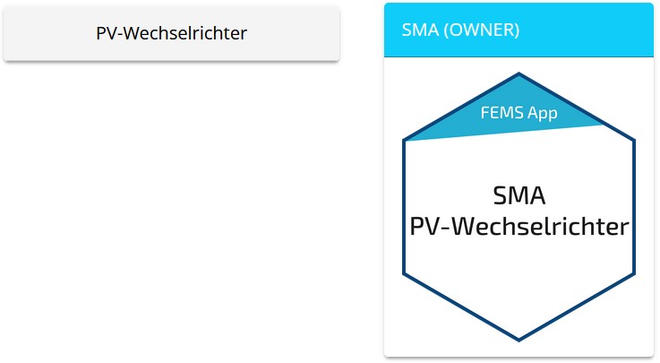
You will then be taken to the app overview:
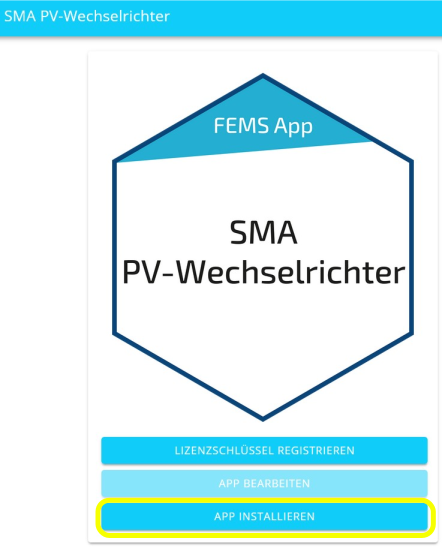
Select the INSTALL APP button.
You will then be taken to the installation wizard for the respective app:
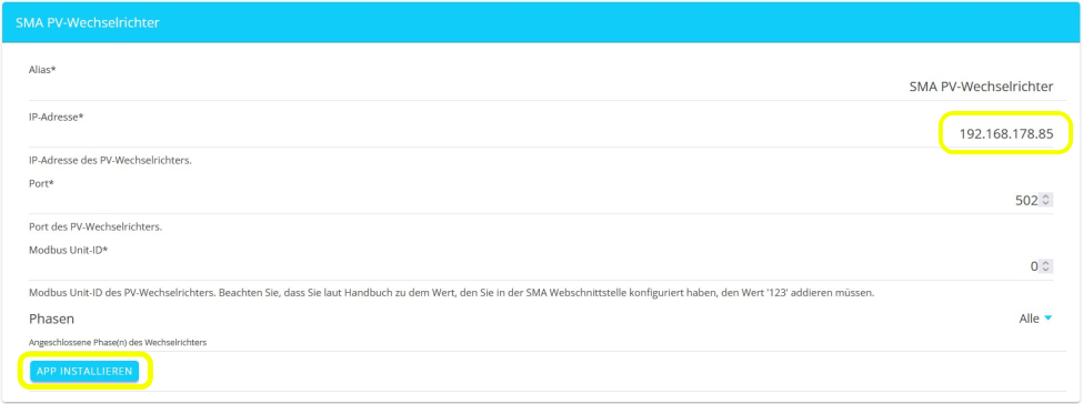
Some of the input fields are pre-filled. Nevertheless, enter your data if it differs from the default values (e. g. IP address). Otherwise, the default values can be retained (e. g. port, Modbus unit ID).
| Mandatory fields are marked with (*) |
| Check your entries and make sure that they are correct. Otherwise the respective app will not work properly! |
Select the INSTALL APP button again.
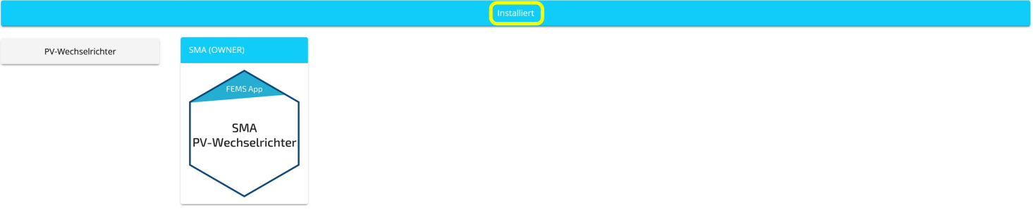
Once the installation process has been successfully completed, the new app will appear in the App Center overview in the Installed category.
10.1.2. Direct installation
You can also install an app directly. To do this, go to the App Center overview and search for the desired app.
| Only apps from the "Available" category can be installed. |
In the example, the FEMS App SMA PV Inverter was searched for. This app is selected by clicking or tapping on the tile.
You will then be taken to the individual view of the app:
Select the INSTALL APP button.
An input mask for redeeming a licence key appears:
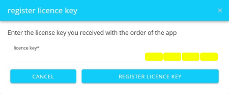
You have two options here:
- Redeem a new licence key directly
-
If you have not yet registered a licence key or wish to redeem a new licence key, enter the 16-digit key in the corresponding field and then click on VALIDATE LICENCE KEY.
The entered licence key is then checked for validity.
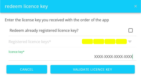
If the licence key is valid, it can be registered by clicking on the button of the same name.
⇒ REDEEM LICENCE KEY
| If the licence key is invalid, please check your entry and try again. |
- Redeem an already registered licence key
-
In this case, the button in the App Center looks like this:

If you want to redeem an already registered licence key, check the corresponding box and select the appropriate, already registered licence key via drop-down menu.
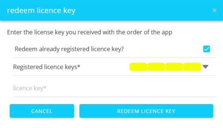
Then click on the REDEEM LICENCE KEY button.
You will then be taken to the installation wizard for the respective app.
Some of the input fields are pre-filled. Nevertheless, enter your data if it differs from the default values (e. g. IP address). Otherwise, the default values can be retained (e. g. port, Modbus unit ID).
| Mandatory fields are marked with (*) |
| Check your entries and make sure that they are correct. Otherwise the respective app will not work properly! |
Select the INSTALL APP button again.
Once the installation process is complete, the new app will appear in the App Center overview in the Installed category.
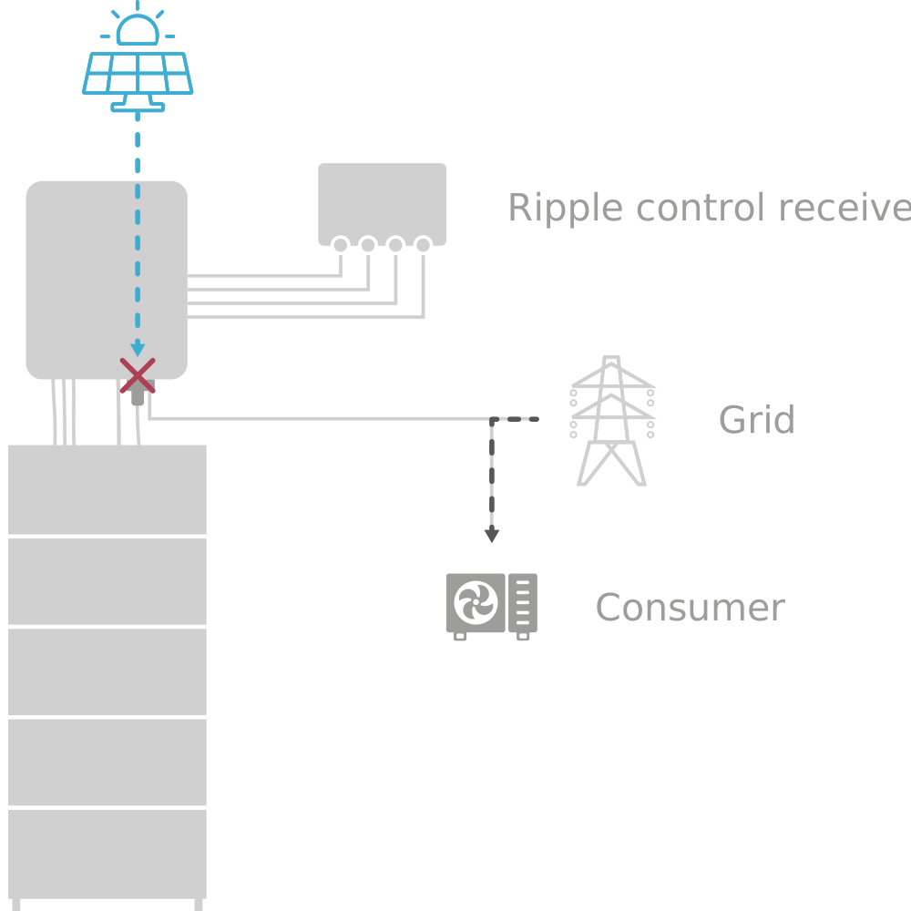
11. External control of the inverter
There are various ways to override the inverter from external devices.
12. Troubleshooting
12.1. Errors in Online Monitoring
The system status can be checked after logging in at the top right using the color of the icon. A green tick indicates that everything is OK, an orange exclamation mark indicates a warning (Warning) and a red exclamation mark indicates an error (Fault).
12.1.1. Fault display

|
System status: Everything is OK |

|
System status: Warning |

|
System status: Error (Fault) |
12.1.2. Troubleshooting

|
You can get a detailed overview of an existing warning or error by clicking on the exclamation mark in the top right-hand corner. |
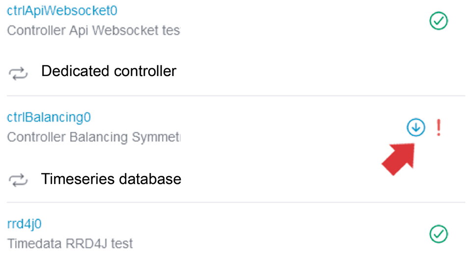
|
The scroll bar can be used to examine the origin of the warning or error in more detail. |
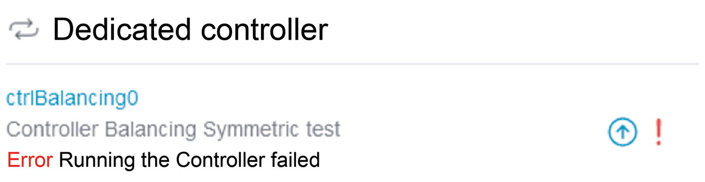
|
Clicking on the icon (down arrow) displays a more detailed error description depending on the error. |
In the example above, an incorrect reference for the grid meter was intentionally entered for test purposes, which is why the controller execution fails.
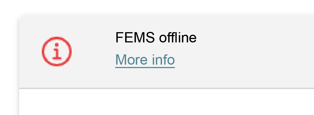
|
Under certain circumstances, it may happen that the FEMS is not accessible and the error message opposite appears. |
If the FEMS is offline, follow the steps displayed below the message.
12.2. Battery tower
12.2.1. Fault display
Faults are displayed on the BMS box via a red LED.
The various errors are indicated by LED codes.
| System status | System information | LEDs | |||||
|---|---|---|---|---|---|---|---|
blue/red |
1 |
2 |
3 |
4 |
|||
Bootloader |
|||||||
Start |
Master/Slave |
||||||
Parallel Box |
|||||||
Extension Box |
|||||||
Check mode |
Individual or parallel connection |
||||||
SoC display |
|||||||
Charging |
0 % to 25.0 % SoC |
||||||
25.1 % to 50.0 % SoC |
|||||||
50.1 % to 75.0 % SoC |
|||||||
75.1 % to 99.9 % SoC |
|||||||
100 % SoC |
|||||||
Discharging and standby |
100 % to 75.1 % |
||||||
75.0 % to 50.1 % |
|||||||
50.0 % to 25.1 % |
|||||||
25.0 % to 0 % |
|||||||
Error |
Overvoltage |
||||||
Undervoltage |
|||||||
Overtemperature |
|||||||
Undertemperature |
|||||||
Overcurrent |
|||||||
SoH too low |
|||||||
Int. communication |
|||||||
Ext. communication |
|||||||
Parallel address error |
|||||||
Module address error |
|||||||
BMS box fuse |
|||||||
Module fuse |
|||||||
Contact error |
|||||||
Insulation error |
|||||||
BMS error |
|||||||
Blue permanently on |
|
Blinking blue |
|
Blue flashing quickly |
|
Red permanently on |
12.2.2. Troubleshooting
If faults cannot be rectified or in the event of faults that are not included in the fault list, contact FENECON Service. Cf. Service.
12.3. Fault list
| Component | Error/fault | Measure |
|---|---|---|
Battery module |
The battery module has become wet |
Do not touch |
Battery module |
The battery module is damaged |
A damaged battery module is dangerous and must be handled with the utmost care. |
12.4. Service
If the system malfunctions, contact the FENECON Service:
Phone: +49 (0) 9903 6280-0
E-mail: service@fenecon.de
Our service hours:
Mon.-Thurs. 08:00 to 12:00 | 13:00 to 17:00
Fri. 08:00 to 12:00 | 13:00 to 15:00
13. Technical maintenance
13.1. Tests and inspections
|
When carrying out inspection work, ensure that the product is in a safe condition. Improperly performed inspections can have serious consequences for people, the environment and the product itself. |
|
Inspection work must only be carried out by trained and qualified specialists. |
|
The maintenance instructions of the component manufacturer must be observed for all individual components. |
Check the product and the cables regularly for visible external damage. In the event of defective components, contact FENECON Service. Repairs must only be carried out by a qualified electrician.
13.2. Cleaning
Cleaning agents: The use of cleaning agents can damage the electrical energy storage unit and its parts.
It is recommended that the electrical energy storage unit and all its parts are only cleaned with a cloth moistened with clean water.
|
The entire product must be cleaned regularly. Only appropriate cleaning agents must be used for this purpose. |
13.3. Maintenance work
No regular maintenance work needs to be carried out on the system. Nevertheless, check the status of your electrical energy storage system regularly.
|
Regular re-referencing of the electrical energy storage system is recommended, i.e. it must be completely discharged (SoC = 0 %) and then fully charged again (SoC = 100 %), as otherwise capacity may be lost. |
13.4. Repairs
In the event of defective components, contact FENECON Service.
13.5. Warranty cases
Warranty claims must be reported to FENECON in text form (e. g. by e-mail) within the warranty period. The notification must be made within a cut-off period of 8 weeks after the end customer has become aware of the warranty claim or could have become aware of it without gross negligence.
14. Advice for fire departments when dealing with FENECON Home & Commercial systems
The FENECON Home and Commercial systems operate in the low-voltage range, which means that they are operated with voltages of less than 1,500 volts direct current (DC) and less than 1,000 volts alternating current (AC).
It may be useful to install an additional switch that disconnects the building from the emergency power supply. This makes it easier for the fire department to act safely and quickly in an emergency.
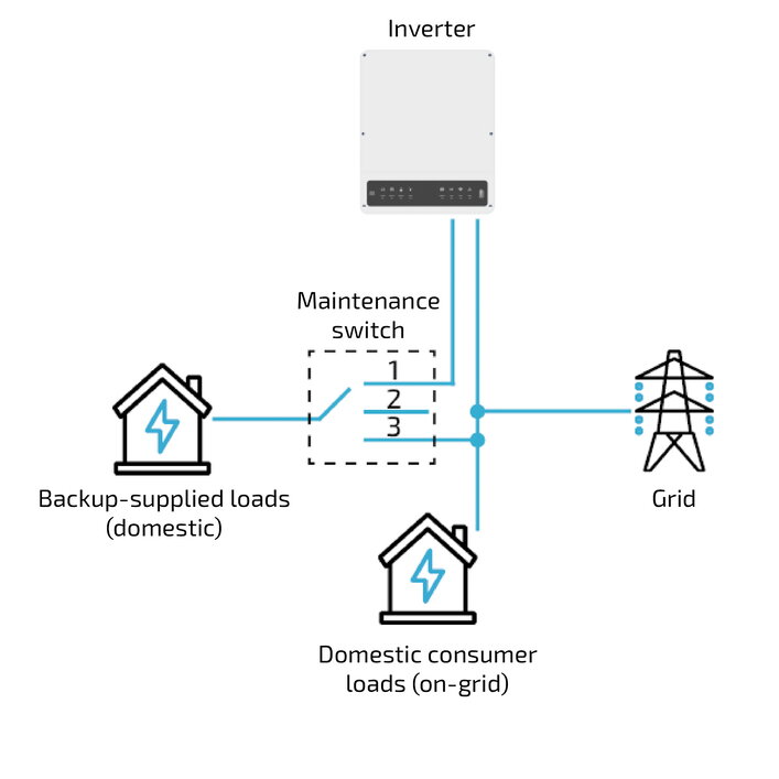
For a precise procedure for emergency services, it is recommended to ask the relevant fire academies and request the corresponding information sheets and pocket cards for battery energy storage systems.
15. Flood safety measures FENECON Home & Commercial
First steps after the water has receded
Even if your battery energy storage system looks undamaged on the outside:
-
Do not put the system back into operation yourself.
-
Ventilate the room well before entering (open windows from the outside if possible).
-
Avoid sparks (no smoking, no lighters).
Why a review is important:
Even though LFP batteries are very safe, water or moisture can:
-
Cause short circuits in the electronics.
-
Trigger corrosion of electrical connections.
-
Create isolation problems that only become apparent later.
These problems do not have to occur immediately, but can develop over weeks.
Commission a professional inspection
Please contact:
-
Your installer or a qualified electrician with experience in battery energy storage systems.
-
FENECON, the manufacturer of your system.
-
Your insurance company — document the damage with photos.
The qualified specialist will check:
-
Whether water has entered the system.
-
Whether electronic components have been damaged.
-
Whether a recommissioning is safely possible or a replacement is necessary.
No recommissioning without approval
Battery energy storage systems that have come into contact with water must only be put back into operation after a professional inspection and express approval by a qualified specialist. This is for your safety and is often also a prerequisite for your insurance cover.
When replacement is necessary
If your electrical energy storage system needs to be replaced:
-
The disposal of the defective system must be carried out professionally by specialized companies.
-
Your installer will usually organize the removal and disposal.
-
Do not attempt to transport damaged batteries yourself
Storage disposal until collection
If damaged battery modules cannot be collected immediately:
-
Store them well ventilated outdoors with sufficient clearance from flammable materials.
Storage in a-
Sand bed.
-
Fireproof container, not gas-tight, ventilated.
-
Water bath, e. g. metal tub, completely covered with water.
-
-
Keep children and pets away.
Status: October 2025
Source: According to Specifications of the German Energy Storage Systems Association (BVES) e.V..
17. Transport
This section contains information on external and internal transportation of the product.
Transportation is the movement of the product by manual or technical means.
-
Only use suitable and tested lifting gear and hoists for transportation!
|
Risk due to lifted loads! |
|
Check that the parts and outer packaging are in perfect condition. |
|
Check that
|
Notes:
|
|
Legal regulations |
18. Dismantling and disposal
18.1. Prerequisites
-
The power supply to the electrical energy storage unit is interrupted and secured against being switched on again.
|
Sharp and pointed edges
|
18.2. Dismantling
-
The electrical energy storage system may only be dismantled by authorized qualified electricians.
-
Dismantling work must only be carried out when the system has been taken out of operation.
-
Before starting disassembly, secure all components to be removed against falling, tipping over or moving.
-
Dismantling work must only be carried out when the system is shut down and only by service personnel.
-
The dismantling instructions of the component manufacturer (→ Appendix, Applicable documents) must be observed.
-
When transporting the battery modules, the current laws, regulations and standards must be observed (e. g. Dangerous Goods Transportation Act — GGBefG).
18.3. Disposal
-
The FENECON electrical energy storage system must not be disposed of with normal household waste.
-
The FENECON electrical energy storage system is RoHS and REACH compliant.
-
Disposal of the product must comply with local regulations for disposal.
-
Avoid exposing the battery modules to high temperatures or direct sunlight.
-
Avoid exposing the battery modules to high humidity or corrosive atmospheres.
-
Dispose of the electrical energy storage system and the batteries it contains in an environmentally friendly manner.
-
Contact FENECON GmbH to dispose of the used batteries.
|