FEMS App Self-Consumption Optimization
1. Introduction
Dear customer,
Thank you for choosing the "FEMS App Self-Consumption Optimization". You are welcome to send us your suggestions so that we can further improve the quality of our products.
2. Installing the app
The FEMS App Self-Consumption Optimization is installed by default on all FENECON Home and Commercial systems.
With FENECON Industrial S, Self-Consumption Optimization can be optionally selected during installation. For all other Industrial systems, FENECON carries out the installation of the app.
3. FEMS App Self-Consumption Optimization
In combination with a PV system, a combined heat and power plant (CHP) or a wind turbine, the Self-Consumption Optimization is the most common application for an electrical energy storage system.
3.1. Functionality
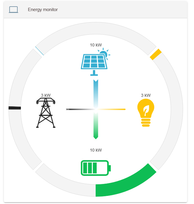
The control algorithm ensures that the proportion of self-used energy ("self-consumption") is optimized. To this end, the electrical energy storage system is always charged when generation is greater than consumption and discharged when generation is insufficient to supply the electrical consumer loads. This is technically equivalent to an adjustment to "0" at the grid connection point, i. e. avoiding grid withdrawal and grid feed-in. Netted active power values (totaled across all three phases) are used here.
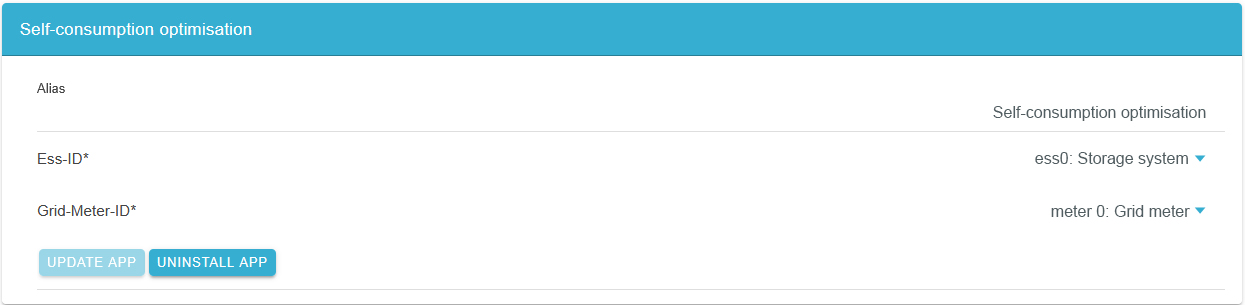
3.2. Visualization and configuration in the Online Monitoring
The amount of self-consumption can be viewed in Online Monitoring via the associated flat widget:
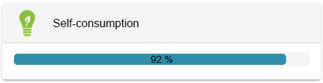
In the example above, self-consumption is 92 %. This means that 92 % of the electricity generated is consumed.
A click on the "History" tab displays the self-consumption as follows:
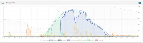
The picture shows: The energy produced by the PV system that is not directly consumed charges the battery (green) until it is full (dashed line). From then on, the surplus energy is fed into the public grid (blue). In the evening, the electrical energy storage system discharges again (red) to supply consumers (yellow).
4. Self-consumption optimization 2.0
|
FENECON offers various FEMS Apps that extend self-consumption optimization and make the electrical energy storage system demonstrably more grid-friendly and economical. |
It is also possible to use surplus PV in controlled consumer loads:
5. Specification of the curtailment point via write access
The SetGridActivePower function makes it possible to specify the behavior of the entire energy management system at the grid connection by dynamically setting the control point of the "self-consumption optimization" controller via Modbus.
|
This is set to zero by default (in the normal EVO). |
5.1. Configuration in the write access widget
The following apps must be installed to use this function:
-
FEMS App Write Access
-
FEMS App Self-Consumption Optimization
The component ctrlBalancing0 must be added to the FEMS App write access:
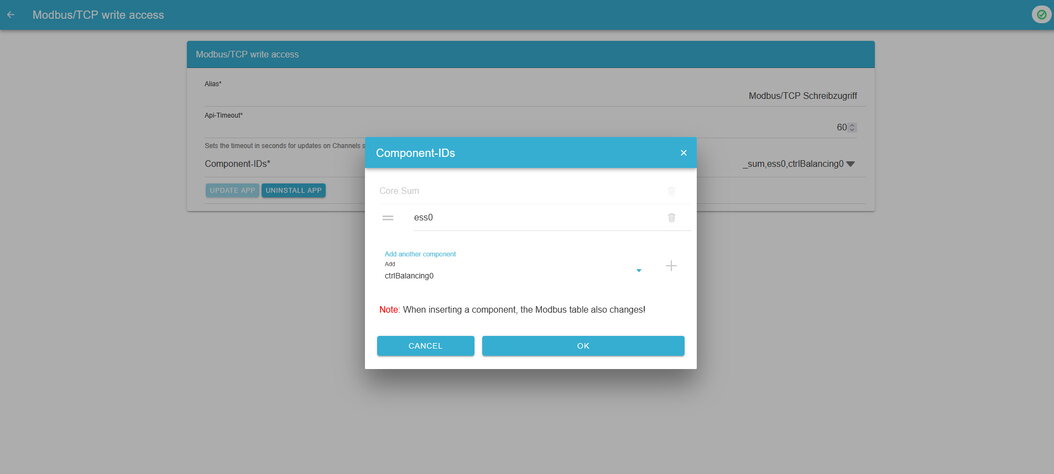
After updating the app, the Modbus data point list must be checked again, as registers may move. An example Modbus list:
890 |
Component-ID |
string16 |
"ctrlBalancing0" |
RO |
906 |
Length of block "ctrlBalancing0" |
uint16 |
"180" |
RO |
910 |
Hash of "OpenemsComponent" |
uint16 |
"0xb3dc" |
RO |
911 |
Length of block "OpenemsComponent" |
uint16 |
"80" |
RO |
912 |
ctrlBalancing0/State |
enum16 |
0:Ok, 1:Info, 2:Warning, 3:Fault |
RO |
990 |
Hash of "ControllerEssBalancingImpl" |
uint16 |
"0xb8b0" |
RO |
991 |
Length of block "ControllerEssBalancingImpl" |
uint16 |
"100" |
RO |
992 |
ctrlBalancing0/SetGridActivePower |
float32 |
WO |
In this example, you can write to 992 to move the setpoint of the self-consumption controller.
5.2. Functionality
SetGridActivePower makes it possible to specify the behavior of the entire energy management system at the grid connection.
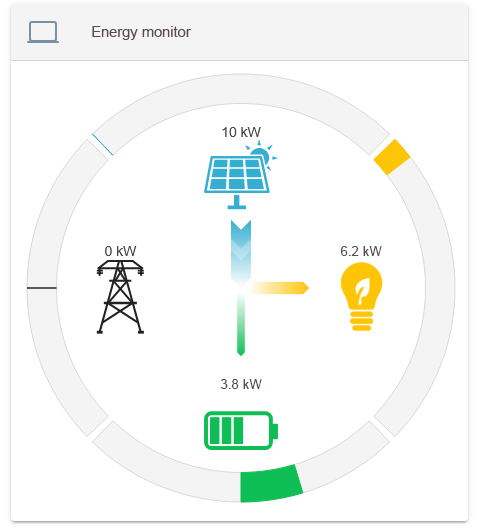
5.2.1. Standard case: Adjustment to zero
The system keeps the grid connection as close to zero as possible:
5.2.2. Default: Negative value (grid feed-in)
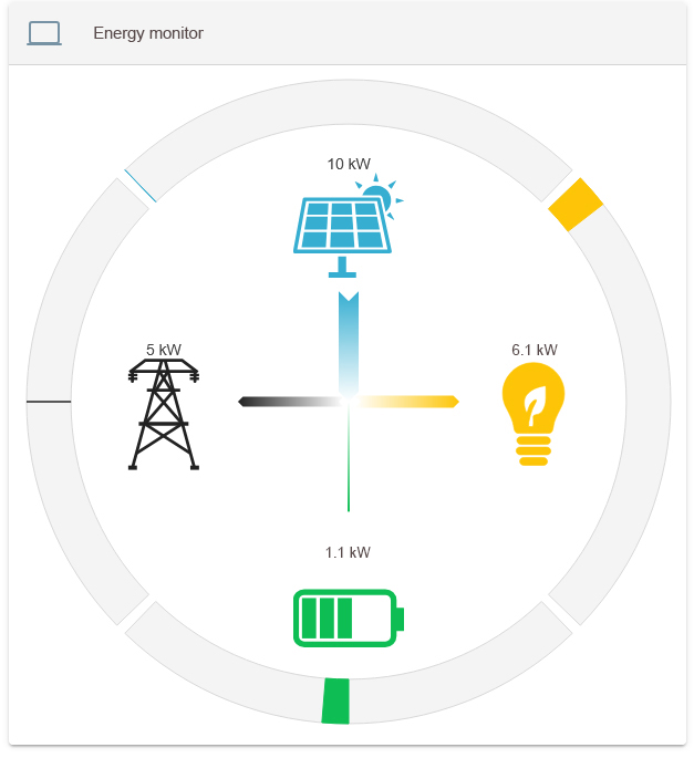
If a negative value is set for SetGridActivePower, the EMS feeds in 5 kW at the grid connection in the example. The electrical energy storage supplements generation and consumption. The generator cannot be controlled.
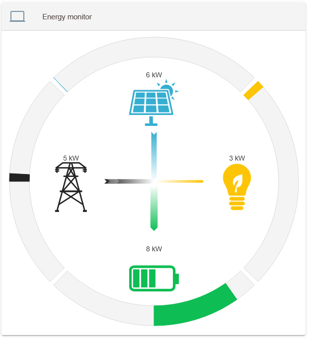
5.3. Borderline cases in implementation
Especially when the electrical energy storage system reaches the limits of its operating range, it may no longer be possible to convert the value. Corresponding consumption or generation can compensate for this. However, this is not controlled by the EMS.