Supplement to the Ordinance on
Installations for Handling Substances Hazardous to Water (AwSV)
1. About this document
2. Handling substances hazardous to water
The FENECON Industrial XL is an above-ground battery energy storage system designed for handling substances hazardous to water in the commercial sector.
The batteries of the energy storage system are housed in a 22-foot steel container. On the outside, the external cooling system is positioned next to the container to ensure constant temperature control. A drip tray is integrated inside at the bottom of the container, as well as inside the cooling system. Both drip trays serve as a barrier for leaking glycol (total approx. 410 l Glysofor L, water hazard class 1). This therefore complies with the requirements of § 35 (3) of the Ordinance on Installations for the Handling of Substances Hazardous to Water ("AwSV").
The air conditioning unit itself will use the gaseous coolant R513A, which has no impact on water management.
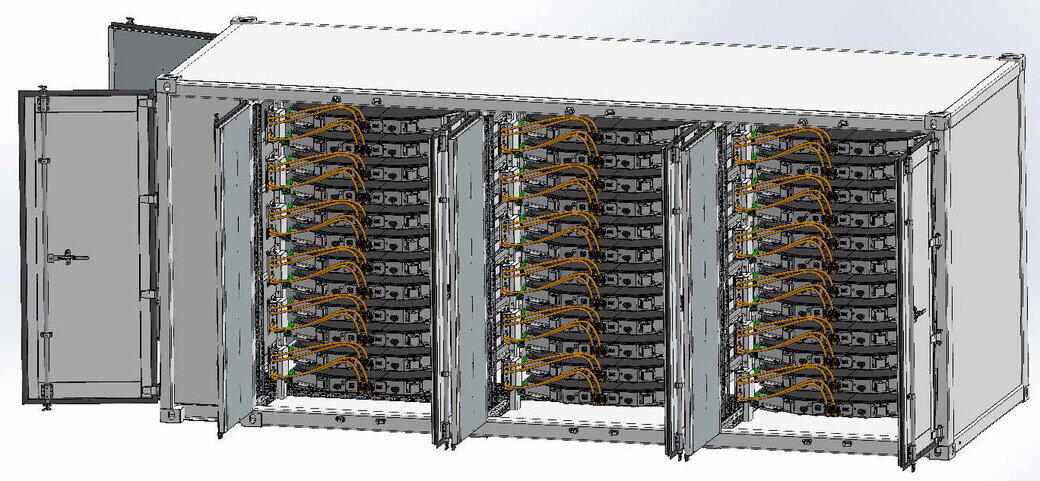
The battery container itself contains the control unit on the left and the remaining container contains 3 battery towers, each with 12 slide-in modules, each with 585 kg per battery pack. According to the manufacturer, the liquid in the battery cell accounts for up to 15 % of the mass, these are substances of Water Hazard Class 1 and 2. According to the mixing rule, Water Hazard Class 2 must be applied to the liquid. The solid mass of the battery also contains cobalt and nickel, which have Water Hazard Class 3. The individual battery cells are automotive battery cells, which are approved for use in road traffic and therefore have a hazardous goods approval. The coolant is fed into the container from the external cooling system via transfer lines through two coolant connections. Inside, it is distributed via the main lines that run along the rear wall of the container. Three branch lines branch off from the main line to the web lines of the respective battery tower. In the event of a leak, the coolant can escape both at the rear of the container and directly in the battery storage area. In this case, it would flow into the collection tray installed at the bottom of the container, which can hold a volume of 820 liters and thus prevent uncontrolled spreading.
3. Calculation of the liquid-retaining drip tray
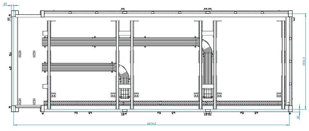
3.2. Key data on the container
| Line and volume data | Container data | ||
|---|---|---|---|
Line volume 0.5 inch in meters |
65.00 |
Container inside dimension length in mm |
6614.00 |
Liquid volume per meter with 0.5 inch line |
0.13 |
Container inside dimension width in mm |
2302.00 |
Volume of 1.5 inch pipe in meters |
26.50 |
Height of container tray in mm |
60.00 |
Liquid volume per meter with 1.5 inch line |
1.14 |
Width of cable duct in mm |
200.00 |
Volume of 0.5 inch cable in meters |
65.00 |
Height of cable duct in mm (height of occupied area) |
200.00 |
Liquid volume per meter with 2.5 inch cable |
3.17 |
Total length of cable duct |
7500.00 |
Amount of batteries |
36.00 |
Length of control cabinet in mm |
1200.00 |
Battery coolant; volume in liters |
3.80 |
Depth of control cabinet in mm |
400.00 |
Water-polluting battery fluid; volume in liters |
65.00 |
External dimensions 2.5-inch pipe in mm |
63.00 |
HYDAC cooling system; tank volume in liters |
65.00 |
||
| Volume calculation in liters | |
|---|---|
Total battery fluid volume hazardous to water |
3164.40 |
Required retention for total water-polluting battery fluid volume |
316.44 |
Total cooling liquid volume |
410.14 |
Required total retention volume |
723.58 |
Volume of bottom tray |
913.53 |
Displaced volume (due to built-up space within the base tray) |
93.07 |
Total retention volume |
820.45 |
Due to the construction method, a drum and container storage facility in accordance with § 31 AwSV can be assumed here. The required retention must therefore be 10% of the total volume of the batteries. The total volume of the liquid is up to 3164 l (88 l x 36 batteries). This means that 317 liters of containment volume must be provided. If there is also an accident in one of the cooling lines, the maximum 410 l of coolant must be added, making a total of 727 l. Due to the mechanical battery enclosure, it is not necessary to retain the solid substances hazardous to water in accordance with Section 26 (1) AwSV. The existing collection tray is therefore sufficiently dimensioned.
4. Classification of the system according to AwSV
The liquid part of the system of max. 3.58 t of Water Hazard Class 2 liquid thus requires a system of hazard level B. The solid part of the batteries with a total weight of max. 17.9 t with substances of Water Hazard Class 3 requires a system of hazard level D. Therefore, the total amount of solid and liquid substances hazardous to water results in hazard level D for the system according to § 39 AwSV sec. 10. According to Annex 5 of the AwSV, this means that the system must be inspected by an expert in accordance with § 47 AwSV before commissioning, after significant changes, periodically every 5 years, and during decommissioning. These are experts in accordance with § 52 and § 53 AwSV.
Furthermore, system documentation in accordance with Section 43 AwSV and operating instructions in accordance with Section 44 AwSV are required for the system. These must be prepared and maintained by the operator of the system.