Installation Manual
1. Information on these installation instructions
These installation instructions are an integral part of the FENECON Industrial L electrical energy storage system and must be kept in its immediate vicinity and accessible to personnel at all times.
Personnel must have carefully read and understood these installation and service instructions before starting any work.
1.1. Manufacturer
FENECON GmbH
Gewerbepark 6
94547 Iggensbach
Germany
Phone +49 (0) 9903 6280 0
Fax +49 (0) 9903 6280 909
E-mail: service@fenecon.de
Website: www.fenecon.de
1.2. About these instructions
© FENECON GmbH, 2025
All rights reserved.
Reprinting, even in part, is only permitted with the permission of FENECON GmbH.
1.3. Version/revision of this manual
| Version/Revision | Änderung der Montageanleitung | Datum | Name |
|---|---|---|---|
V0 |
Entwurf Ersterstellung |
23.05.2023 |
FENECON GmbH |
2025.04.01 |
Übernahme auf docs.fenecon.de |
10.04.2025 |
FENECON PM |
1.4. Symbol conventions
|
||
|
||
|
||
|
||
|
1.5. Structure of warning notices
If observed, warnings protect against possible personal injury and damage to property. The signal word to classifies the magnitude of danger.
Warnings are structured according to the SAFE method:
| Signal word | Meaning |
|---|---|
S |
Signal word: (DANGER, WARNING, CAUTION or NOTICE) |
A |
Type and source of danger: |
F |
Consequence: |
E |
Event: |
|
Source of the danger
|
2. Scope of delivery
2.1. Standard parts
| Item | Description | Amount | Item no. |
|---|---|---|---|
01 |
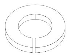
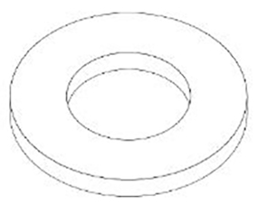
Spring washer D10.2 |
72 |
ZUI012 |
02 |
Disc washer D10.5 |
154 |
ZUI029 |
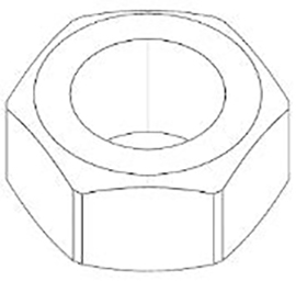
03 |
Hexagon nut M10 |
76 |
ZUI128 |
04 |
Hexagon head bolt, fully threaded M10 x 30 |
48 |
ZUS133 |
05 |
Hexagon head bolt, fully threaded M10 x 25 |
24 |
ZUS088 |
06 |
Screw, flattened, hexagon socket M6 x 10 |
28 |
ZUS302 |
07 |
Spring washer D8.1 |
32 |
ZUS056 |
08 |
Disc washer D8.4 |
64 |
ZUS162 |
09 |
Hexagon nut M8 |
32 |
ZUI006 |
10 |
Hexagon head bolt, fully threaded M8 x 22 |
32 |
ZUS789 |
11 |
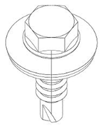
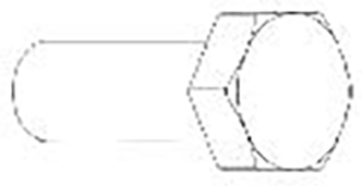
Bolt anchor HST3-R M16 x 135 35/15 |
12 |
ZUS791 |
12 |
EJOT self-drilling screw JT6-6-5.5 |
40 |
ZUS792 |
13 |
Cylinder head bolt with hexagon socket M10 x 80 |
4 |
ZUS790 |
14 |
Hexagon head bolt, fully threaded M10 x 18 |
2 |
ZUS788 |
15 |
Cable duct 200 x 50 |
4 |
KAI057 |
16 |
Earth circuit connector |
1 |
ZUS787 |
|

|
|
|
72 x ZUI012 |
154 x ZUI029 |
76 x ZUS128 |
48 x ZUS133 |
|
|
|
|
24 x ZUS088 |
28 x ZUS302 |
32 x ZUS056 |
64 x ZUS162 |

|

|
|
|
32 x ZUI006 |
32 x ZUS789 |
12 x ZUS791 |
40 x ZUS792 |
|
|
|
|
4 x ZUS790 |
2 x ZUS788 |
4 x KAI057 |
1 x ZUS787 |
2.2. Components
| Pos. | Description | Amount | Item no. |
|---|---|---|---|
17 |
Steel frame 01 |
3 |
GE1 (ZUI997) |
18 |
Steel frame 02 |
4 |
GE2 (ZUI997) |
19 |
Steel frame 03 |
2 |
GE3 (ZUI997) |
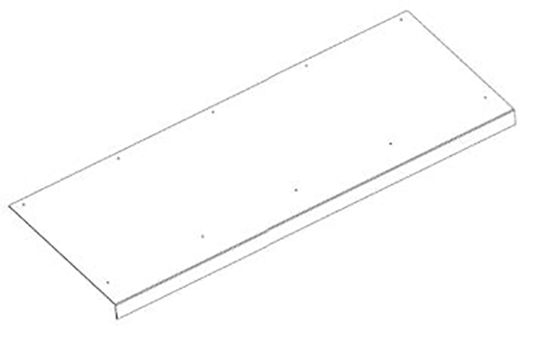
20 |
Lid 01 |
8 |
DE1 (ZUI997) |
21 |
Cover 02 |
4 |
DE2 (ZUI997) |
22 |
Cover 03 |
4 |
DE3 (ZUI997) |
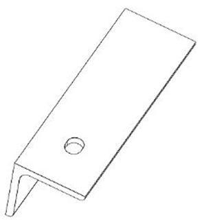
23 |
Sheet metal roof 01 |
2 |
DB1 (ZUI997) |
24 |
Sheet metal roof 02 |
2 |
DB2 (ZUI997) |
25 |
T-shaped connector 01 |
2 |
PE1 (ZUI997) |
26 |
T-shaped connector 02 |
2 |
PE2 (ZUI997) |
|
|
|
3 x GE1 |
4 x GE2 |
2 x GE3 |
|
|
|
8 x DE1 |
4 x DE2 |
4 x DE3 |
|
|
|
2 x DB1 |
2 x DB2 |
2 x PE1 |
|
||
2 x PE2 |
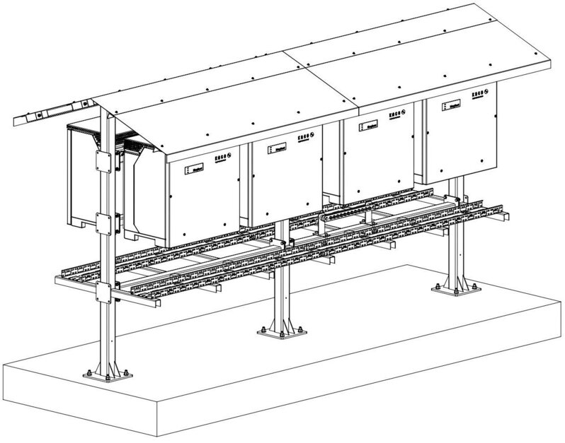
3. Assembly
3.1. Residual risks
|
Danger to life due to fire or explosion
|
|
Property damage caused by gases that react aggressively to surfaces in conjunction with weather-related humidity.
→ In the event of non-compliance, material damage to the device is not covered by the warranty. |
|
Access by maintenance personnel in case of service
|
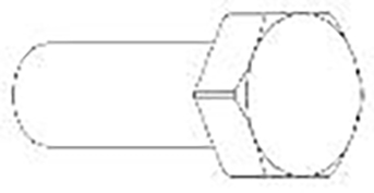
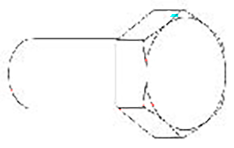
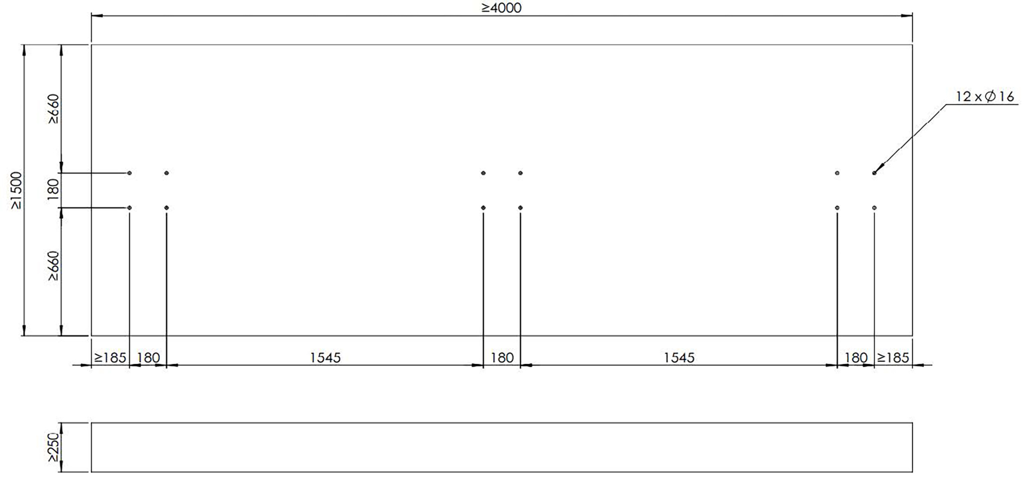
3.2. Foundation
-
We recommend preparing a foundation on site for the assembly of the inverter rack.
-
This foundation must be designed by the customer, taking into account the statics.
-
Please refer to the following image for the connection drilling diagrams.
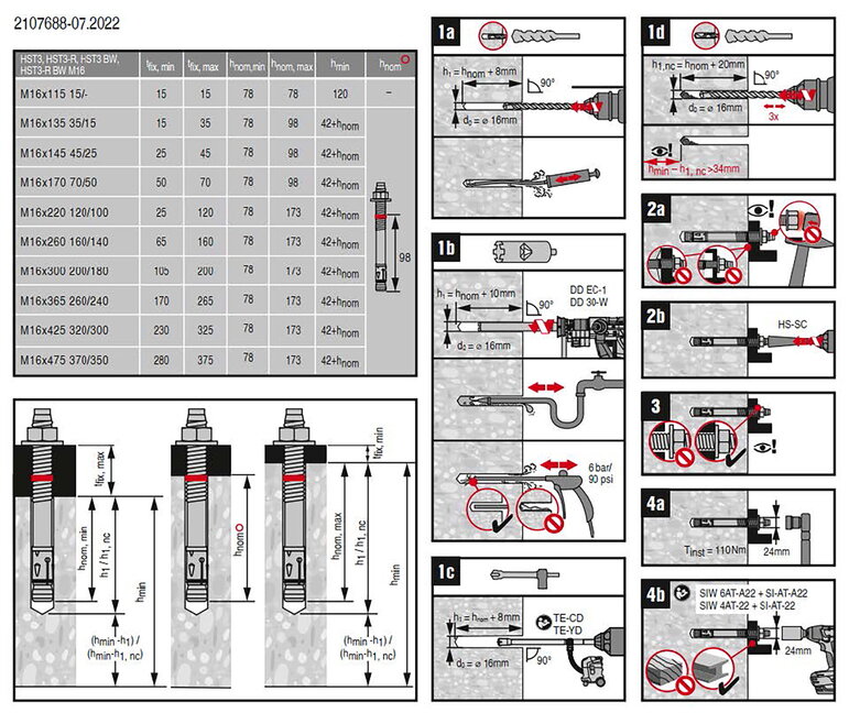
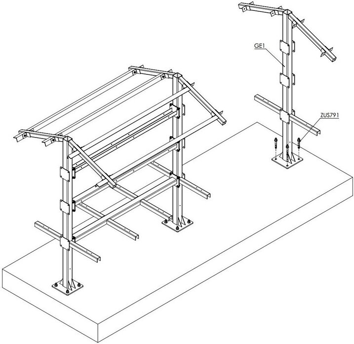
3.3. Ground anchor
We recommend fastening the inverter rack using ground anchors. Please use the enclosed ground anchors (list item 11 in the parts list: ZUS791).
(Hilti bolt anchor HST3-R M16 x 135 35/15 #2105876)
Please also observe the manufacturer’s setting instructions.
Please also note the torque of the bolt anchor (ZUS791).
The recommended torque is 110 Nm.
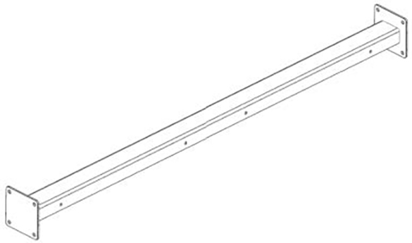
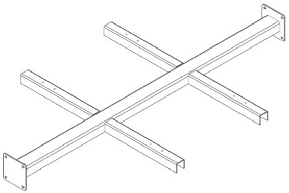
3.4. Assembly of the inverter rack
Step 1:
You need:
| Description | Amount | Item no. |
|---|---|---|
Bolt anchor HST3-R M16 x 135 35/15 |
8 |
ZUS791 |
Steel frame 01 |
2 |
GE1 (ZUI997) |
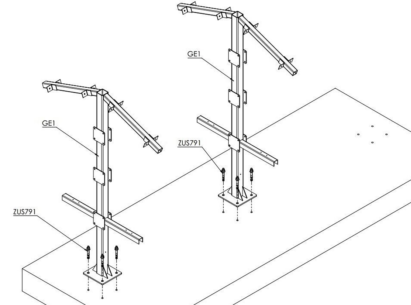
-
Anchor the first two frame elements to the foundation.
-
Use 4 pieces of ZUS971 (list item 11) for each stand.
-
Observe the specified torque of the bolt anchor: 110 Nm.
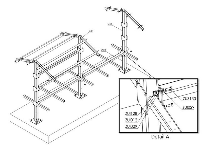
Step 2:
You need:
| Description | Amount | Item no. |
|---|---|---|
Spring washer D10.2 |
8 |
ZUI012 |
Disc washer D10.5 |
16 |
ZUI029 |
Hexagon nut M10 |
8 |
ZUS128 |
Hexagon head bolt, fully threaded M10 x 30 |
8 |
ZUS133 |
Steel frame 03 |
1 |
GE3 (ZUI997) |
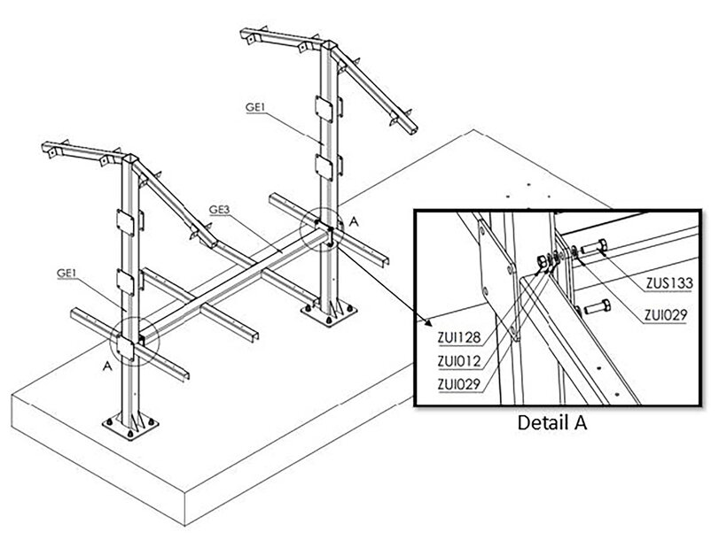
-
Bolt the frame element GE3 to the frame elements GE1 on both sides.
-
Use the components in "Detail A" of Image GE3, GE1 (detailed view).
-
Observe the permissible torque: 50 Nm.
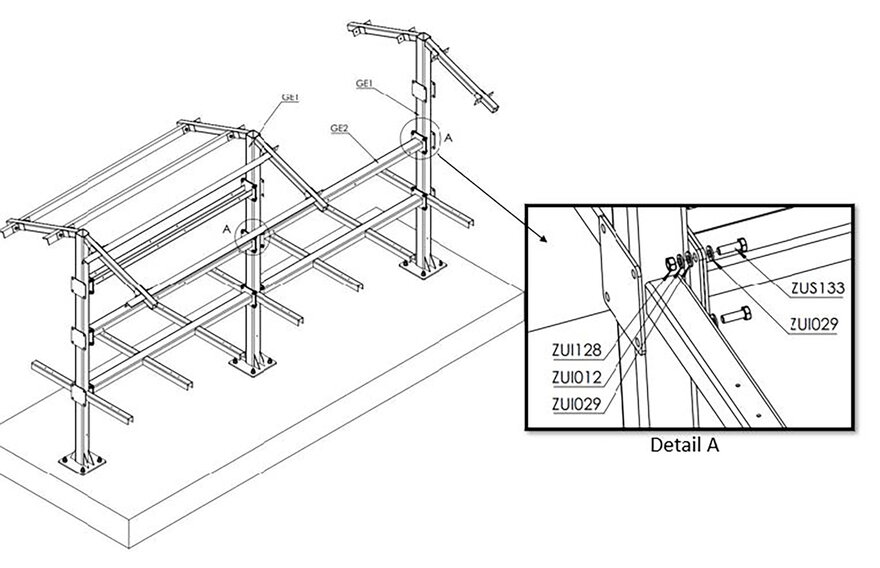
Step 3:
You need:
| Description | Amount | Item no. |
|---|---|---|
Spring washer D10.2 |
8 |
ZUI012 |
Disc washer D10.5 |
16 |
ZUI029 |
Hexagon nut M10 |
8 |
ZUS128 |
Hexagon head bolt, fully threaded M10 x 30 |
8 |
ZUS133 |
Steel frame 02 |
1 |
GE2 (ZUI997) |
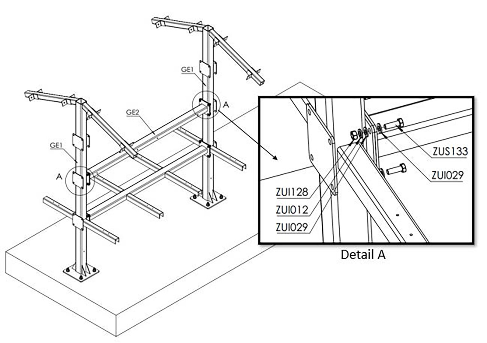
-
Bolt the frame element GE2 to the frame element GE1.
-
Use the components in "Detail A" of Image GE2, GE1.
-
Caution: Attach the frame element GE2 so that the U-profile is positioned with the opening facing downwards.
-
Observe the permissible torque: 50 Nm.
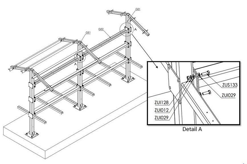
Step 4:
You need:
| Description | Amount | Item no. |
|---|---|---|
Spring washer D10.2 |
8 |
ZUI012 |
Disc washer D10.5 |
16 |
ZUI029 |
Hexagon nut M10 |
8 |
ZUS128 |
Hexagon head bolt, fully threaded M10 x 30 |
8 |
ZUS133 |
Steel frame 03 |
1 |
GE2 (ZUI997) |
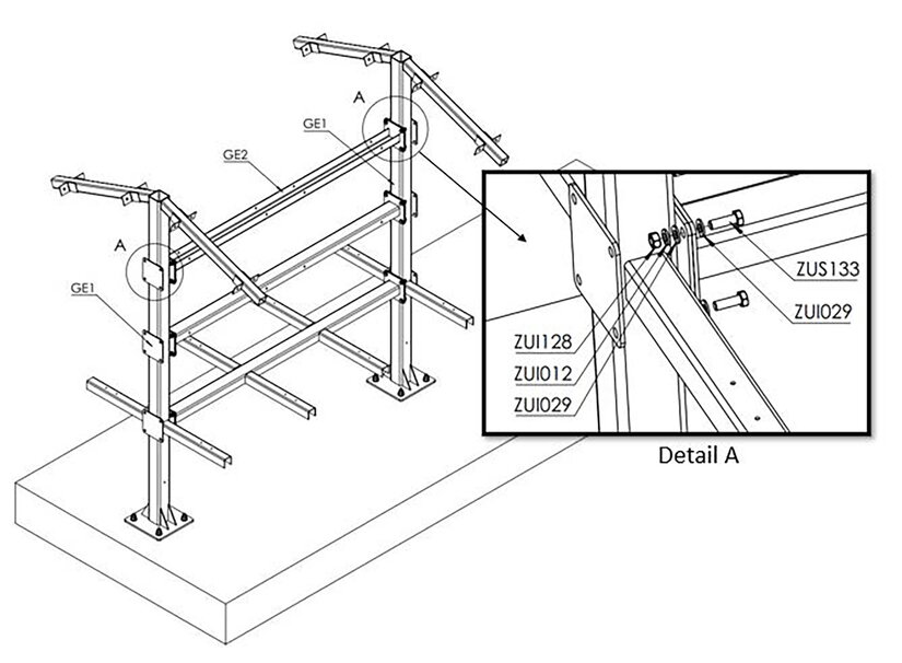
-
Bolt the frame element GE2 to the frame elements GE1.
-
Use the components in "Detail A" of Image GE2-2, GE1.
-
Caution: Attach the frame element GE2 so that the U-profile is positioned with the opening facing up.
-
Observe the permissible torque: 50 Nm.
Step 5:
You need:
| Description | Amount | Item no. |
|---|---|---|
Spring washer D10.2 |
4 |
ZUI012 |
Disc washer D10.5 |
8 |
ZUI029 |
Hexagon nut M10 |
4 |
ZUS128 |
Hexagon head bolt, fully threaded M10 x 25 |
4 |
ZUS088 |
Cover 02 |
2 |
DE2 (ZUI997) |
Cover 03 |
2 |
DE3 (ZUI997) |
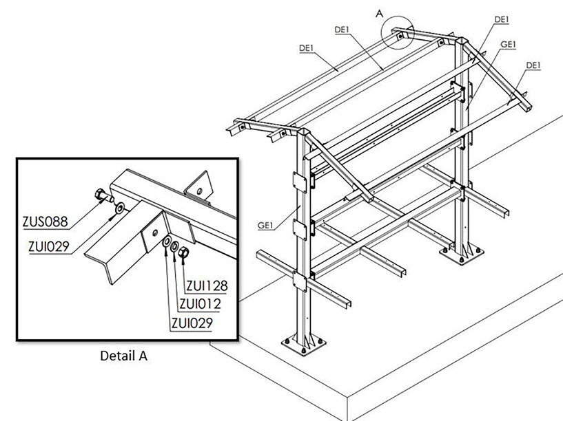
-
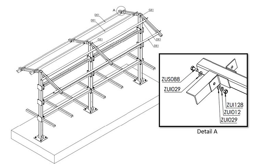
Bolt the roof elements DE2 and DE3 to the frame element GE1.
-
To do this, use the components in "Detail A" of Image DE2-DE3, GE1.
-
Please also note the components in "Detail A" and the permissible torque: 50 Nm.

Step 6:
You need:
| Description | Amount | Item no. |
|---|---|---|
Spring washer D10.2 |
4 |
ZUI012 |
Disc washer D10.5 |
8 |
ZUI029 |
Hexagon nut M10 |
4 |
ZUS128 |
Hexagon head bolt, fully threaded M10 x 25 |
4 |
ZUS088 |
Cover 01 |
4 |
DE1 (ZUI997) |
-
Bolt the roof elements DE1 to the frame element GE1.
-
To do this, use the components in "Detail A" of Image DE1, GE1.
-
Observe the permissible torque: 50 Nm.
Step 7:
You need:
| Description | Amount | Item no. |
|---|---|---|
Steel frame 01 |
1 |
GE1 (ZUI997) |
Bolt anchor HST3-R M16 x 135 35/15 |
4 |
ZUS791 |
-
Place the third frame element on the foundation and anchor it.
-
Use the "Detail A" components of Image Third GE1 for this.
-
Please refer to the section ground anchor of these installation instructions and the specified torque of the bolt anchor: 110 Nm.
Step 8:
You need:
| Description | Amount | Item no. |
|---|---|---|
Spring washer D10.2 |
8 |
ZUI012 |
Disc washer D10.5 |
16 |
ZUI029 |
Hexagon nut M10 |
8 |
ZUS128 |
Hexagon head bolt, fully threaded M10 x 30 |
8 |
ZUS133 |
Steel frame 03 |
1 |
GE3 (ZUI997) |
-
Bolt the frame element GE3 to the frame element GE1.
-
Use the components in "Detail A" of Image GE3-2, GE1.
-
Please also note the assembly of the components in "Detail A" and the permissible torque: 50 Nm.
Step 9:
You need:
| Description | Amount | Item no. |
|---|---|---|
Spring washer D10.2 |
8 |
ZUI012 |
Disc washer D10.5 |
16 |
ZUI029 |
Hexagon nut M10 |
8 |
ZUS128 |
Hexagon head bolt, fully threaded M10 x 30 |
8 |
ZUS133 |
Hexagon head bolt, fully threaded M10 x 25 |
8 |
ZUS088 |
Steel frame 02 |
1 |
GE2 (ZUI997) |
-
Bolt the frame element GE2 to the frame element GE1.
-
Use the components in "Detail A" of Image GE2-3, GE1.
-
Caution: Attach the frame element GE2 so that the U-profile is positioned with the opening facing downwards.
-
Observe the permissible torque: 50 Nm.
Step 10:
You need:
| Description | Amount | Item no. |
|---|---|---|
Spring washer D10.2 |
8 |
ZUI012 |
Disc washer D10.5 |
16 |
ZUI029 |
Hexagon nut M10 |
8 |
ZUS128 |
Hexagon head bolt, fully threaded M10 x 30 |
8 |
ZUS133 |
Hexagon head bolt, fully threaded M10 x 25 |
8 |
ZUS088 |
Steel frame 02 |
1 |
GE2 (ZUI997) |
-
Bolt the frame element GE2 to the frame element GE1.
-
Use the components in "Detail A" of Image GE2-4, GE1.
-
Caution: Attach the frame element GE2 so that the U-profile is positioned with the opening facing up.
-
Observe the permissible torque: 50 Nm.
Step 11:
You need:
| Description | Amount | Item no. |
|---|---|---|
Spring washer D10.2 |
4 |
ZUI012 |
Disc washer D10.5 |
8 |
ZUI029 |
Hexagon nut M10 |
4 |
ZUS128 |
Hexagon head bolt, fully threaded M10 x 25 |
4 |
ZUS088 |
Cover 01 |
4 |
DE1 (ZUI997) |
-
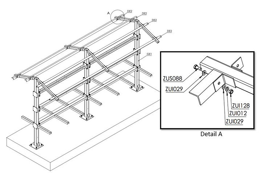
Bolt the roof elements DE1 to the frame element GE1.
-
To do this, use the components in "Detail A" of Image DE1-2, GE1.
-
Observe the permissible torque: 50 Nm.
Step 12:
You need:
| Description | Amount | Item no. |
|---|---|---|
Spring washer D10.2 |
4 |
ZUI012 |
Disc washer D10.5 |
8 |
ZUI029 |
Hexagon nut M10 |
4 |
ZUS128 |
Hexagon head bolt, fully threaded M10 x 25 |
4 |
ZUS088 |
-
Bolt the roof elements DE1 to the frame element GE1.
-
To do this, use the components in "Detail A" of Image DE1-3, GE1.
-
Observe the permissible torque: 50 Nm.
Step 13:
You need:
| Description | Amount | Item no. |
|---|---|---|
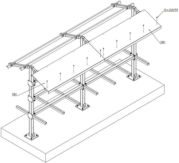
EJOT self-drilling screw JT6-6-5.5 |
10 |
ZUS792 |
Sheet metal roof 01 |
2 |
DB1 (ZUI997) |
-
Screw the sheet metal roofs DB1 to the steel structure.
-
Please only screw the bottom row tight.
Step 14:
You need:
| Description | Amount | Item no. |
|---|---|---|
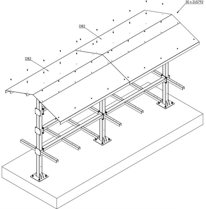
EJOT self-drilling screw JT6-6-5.5 |
30 |
ZUS792 |
Sheet metal roof 02 |
2 |
DB2 (ZUI997) |
-
Screw the sheet metal roofs DB2 to the steel structure.
-
We recommend sealing the overlapping and sealing seams with silicone (transparent) on site.
3.5. Assembly of the inverters
You need:
| Description | Amount | Item no. |
|---|---|---|
Spring washer D8.1 |
4 |
ZUS056 |
Disc washer D8.4 |
8 |
ZUS162 |
Hexagon nut M8 |
4 |
ZUI006 |
Hexagon head bolt, fully threaded M8 x 22 |
4 |
ZUS789 |
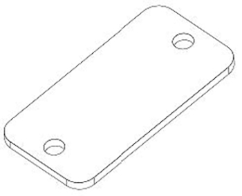
Please note:
The mounting plate is included in the scope of delivery of the inverter. Please refer to the complete delivery for the supplied inverters and mounting plates.
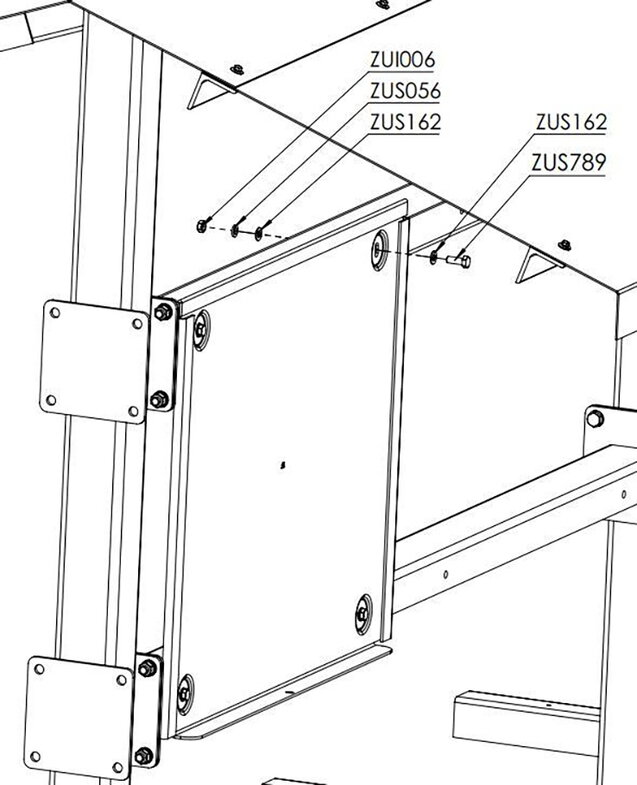
Figure 18. Mounting plate — KACO
|
|
For the further installation steps of the inverters, please refer to the description in the manufacturer’s manual under the following link (from page 16):
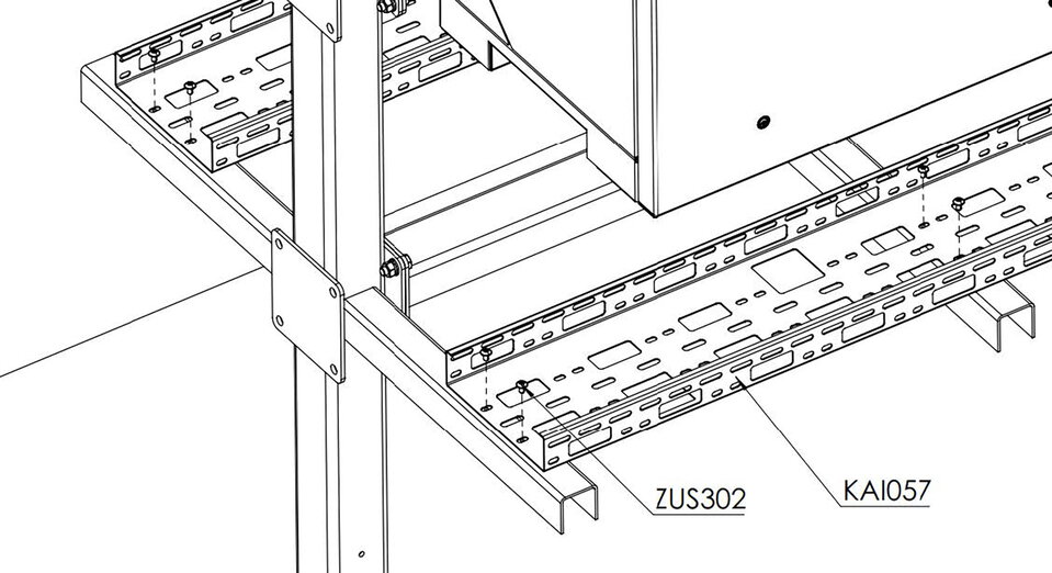
3.6. Assembly of the cable ducts
You need:
| Description | Amount | Item no. |
|---|---|---|
Screw flattened, hexagon socket M6 x 10 |
28 |
ZUS302 |
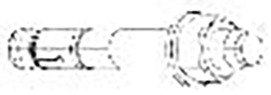
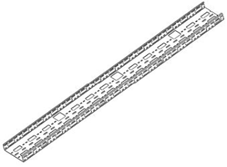
Cable duct 200 x 50 |
4 |
KAI057 |
-
Bolt the 4 cable channels together as shown in the image Assembly — Cable channels.
-
Use the bolts with the description ZUS302 for fastening.
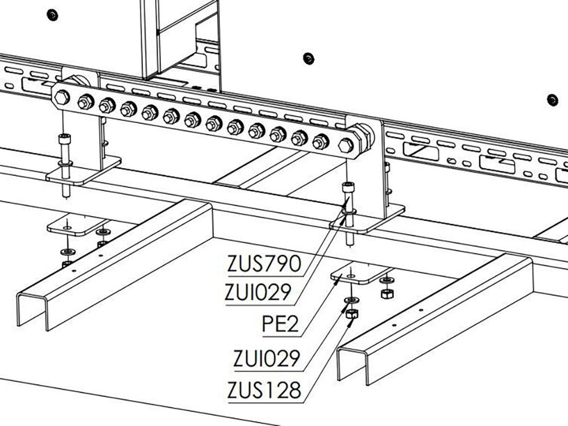
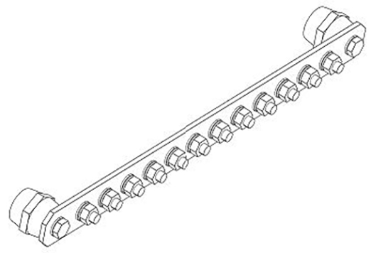
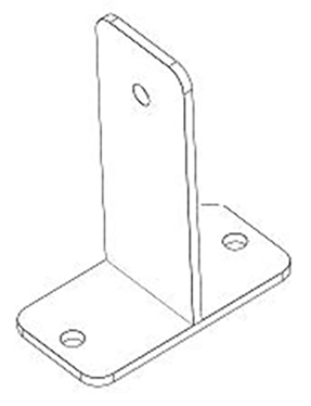
3.7. Assembly of the earth circuit connector
You need:
| Description | Amount | Item no. |
|---|---|---|
Earth circuit connector |
1 |
ZUS787 |
T-shaped connector 01 |
2 |
PE1 (ZUI997) |
T-shaped connector 02 |
2 |
PE2 (ZUI997) |
Disc washer D10.5 |
8 |
ZUI029 |
Hexagon nut M10 |
4 |
ZUS128 |
Cylinder head bolt with hexagon socket M10 x 80 |
4 |
ZUS790 |
Hexagon head bolt, fully threaded M10 x 18 |
2 |
ZUS788 |
-
Mount the potential equalization rail to the bracket as shown in the image earth circuit connector.
-
Observe the permissible torque: 20 Nm.
-
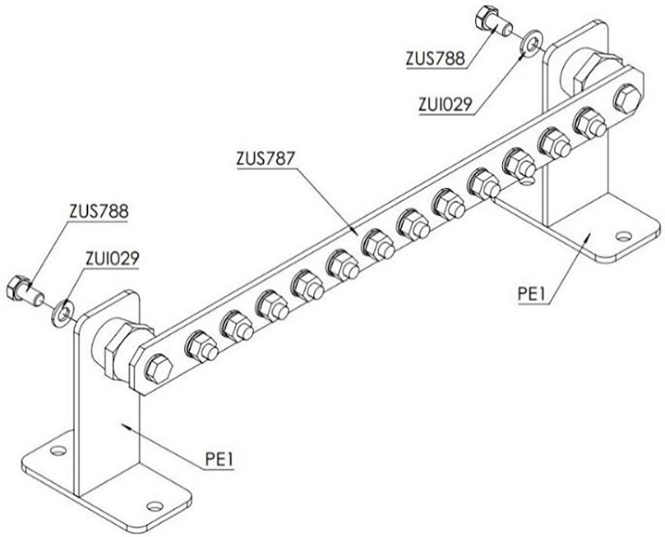
-
Bolt the earth circuit connector with the bracket to the inverter rack as shown in the image Earth circuit connector — Assembly.
-
Observe the permissible torque: 40 Nm.
-