Installation and Configuration Manual — FEMS Package 3-Phase Sensor without Current Transformer (SOCOMEC DIRIS A-10)
1. Introduction
1.1. Legal provisions
Unless stated otherwise, the information contained in these documents is the property of FENECON GmbH. Publication, in whole or in part, requires the written consent of FENECON GmbH.
Diese Anleitung stellt keinen Anspruch auf Vollständigkeit und Korrektheit dar. Sie dient lediglich als Kurzfassung der originalen Anleitung von SOCOMEC. Diese finden Sie hier .
Subject to changes and printing errors!
1.2. Qualification of the installer
A qualified installer is a person who has the following experience and training:
-
Setting up, switching on, switching off, disconnecting, earthing, short-circuiting and repairing circuits and devices
-
Standard maintenance and use of protective devices in accordance with current safety standards
-
First aid/emergency care
-
Current knowledge of local regulations, standards and guidelines
2. Product description
2.1. Scope of delivery
After you have received the delivery, check that all components have been included. Inspect the scope of delivery for damage. If anything is missing or damaged, please contact the supplier immediately. The following components are included in the delivery:
-
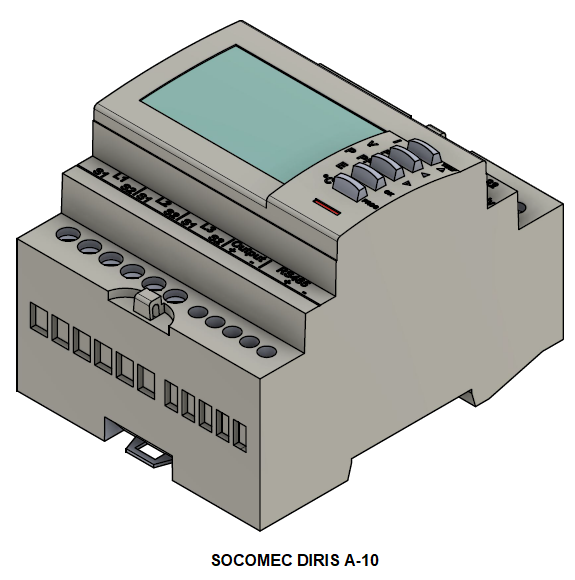
SOCOMEC DIRIS A-10 3-phase sensor
-
Installation and configuration instructions for FEMS package 3-phase sensor without current transformer
-
Montageanleitung für SOCOMEC DIRIS A-10 (hier )
2.2. Prerequisites
The following is required for using the 3-phase sensor:
-
Current transformer
|
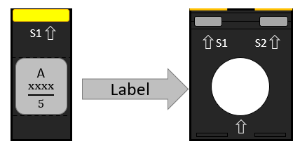
Please note! The current transformers are not included in the scope of delivery! In the example of the SOCOMEC meter, the transformer ratio is 5. You can read the transformer ratio on the current transformers installed on site (see type label, for example). |
3. Connection
3.1. Voltage tap and power supply
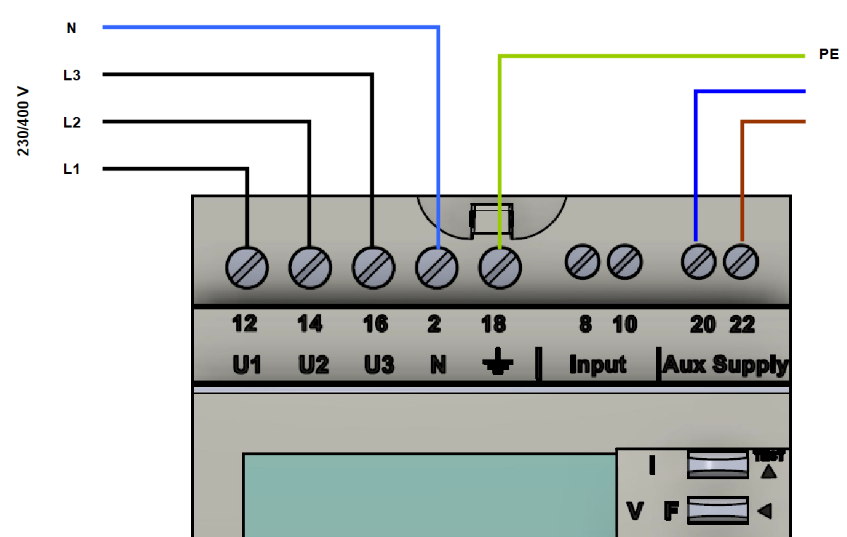
The meter is electrically connected through the three phases and the neutral conductor in accordance with the original instructions. As this type of meter can only work with external current measurement sensors, this is a voltage tap of the three phases and the neutral conductor. In addition to the voltage tap, an additional auxiliary supply voltage (terminals 20 & 22) must be applied to the meter, which is referred to here as "Aux Supply", see
| Cross-section of measuring cable | Max. cable length of current transformer | Max. cable length of voltage tap |
|---|---|---|
2.5 mm² |
up to 3 m |
15 m |
4 mm² |
up to 5 m |
up to 25 m |
3.2. Connection of current transformer to generator
The current transformers must be connected to the generator (inverter) as shown below:
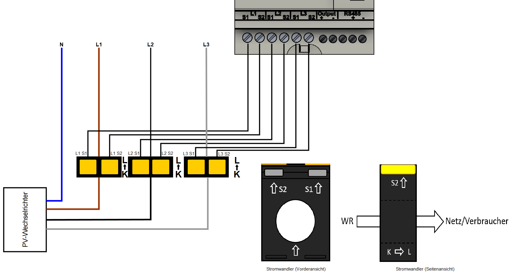
|
Ensure that the transformers are aligned correctly from K to L! |
3.3. Connection of current transformers to the meter of the metering point operator
The current transformers must be connected to the meter of the metering point operator as shown below:
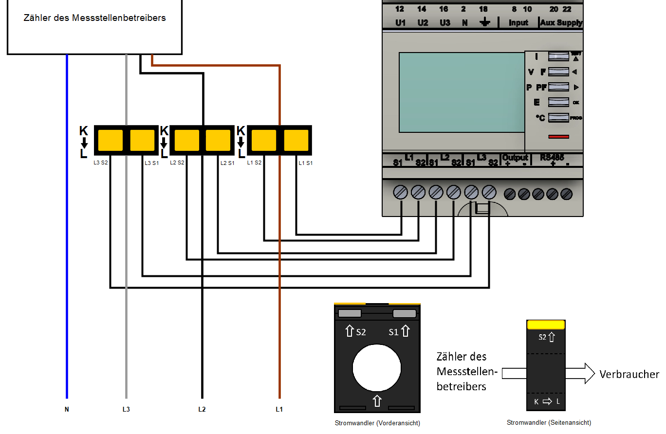
|
Ensure that the transformers are aligned correctly from K to L! |
3.4. Connection of current transformer to consumer load(s)
The current transformers must be connected to a consumer load as shown below:
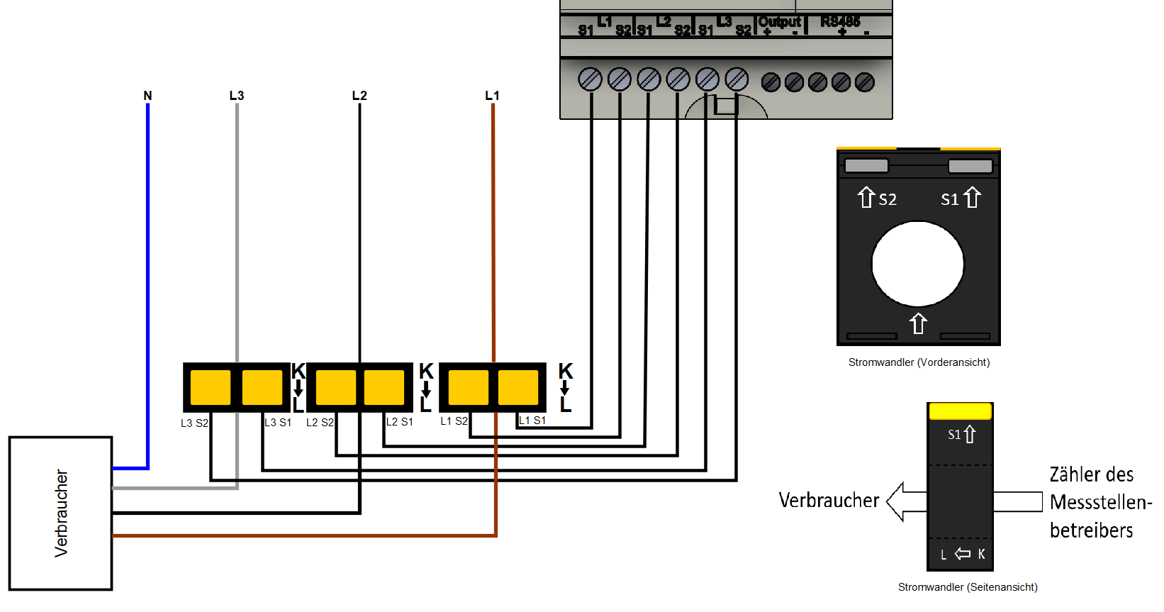
|
Ensure that the transformers are aligned correctly from K to L! |
|
In contrast to the connection to a generator or the meter of the metering point operator, the current transformers must be installed upside down here! |
4. Communication
The Modbus communication available on the DIRIS A-10 is via a serial RS485 interface (2 or 3 wire), which allows the device to be operated from FEMS. In the standard configuration, 32 devices can be connected to a PC or a controller over 1200 meters using an RS485 interface.
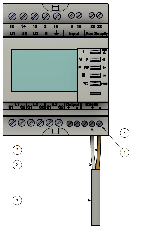
-
COM RS-485 connection from FEMS
-
Data conductor plus (+) (A conductor)
-
Data conductor minus (-) (B conductor)
-
Minus (-) contact
-
Plus (+) Contact
To connect several meters in series, the RS-485 connection must be looped through, as shown in the figure below.
Note the connection of the terminating resistor (120 Ω)!
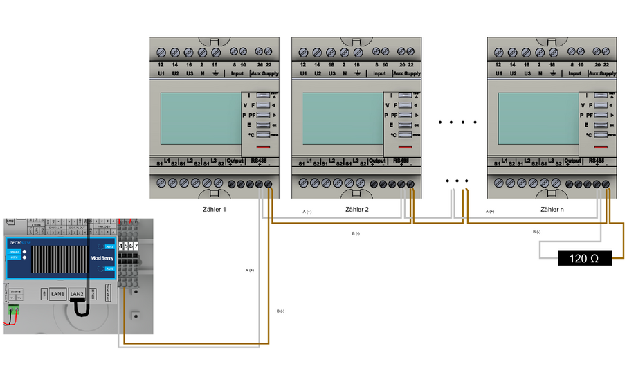
|
If the supplied RS485 cable is not long enough, we recommend using a LiYCY with a cross-section of 0.5 mm². This is suitable for max. 500 m. In general, the manufacturer’s specifications and recommendations must be observed. |
5. Overview of controls
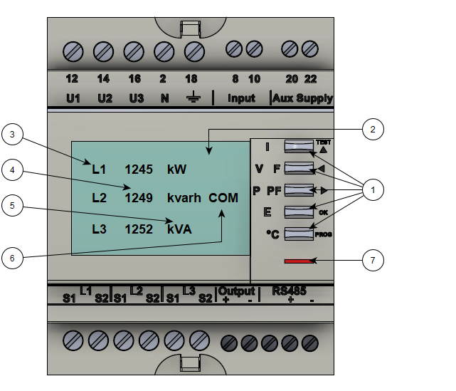
-
Five buttons with dual functionality (display or configuration)
-
Backlit LCD screen
-
Phase
-
Values
-
Unit
-
Activity display communication bus
-
Pointer for recording the active power
6. Configuration
The following configuration settings must be used for use with FEMS:
| Measuring transformer current ratio |
…/5 e. g. 500/5 = 500 A. |
| Baud rate for communication |
9.6 |
| RS485 Modbus address grid connection point |
005 |
| RS485 Modbus address PV generation |
006 |
| RS485 Modbus address — other generators/consumers |
007…246 |
|
Follow the installation and service instructions for the meter installed to make the settings. The following steps are for simplification purposes only. |
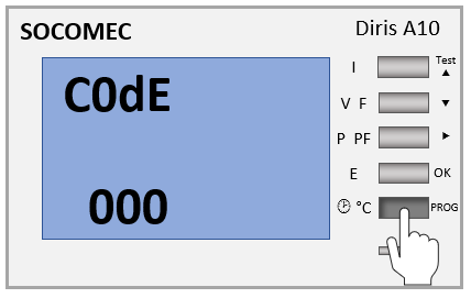
6.1. Password entry
The following steps describe the procedure for entering the password.
-
Press and hold the PROG button for 3 seconds.
-
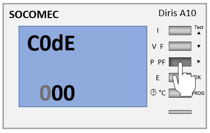
Press the ⇒ button. Then, the first digit flashes.
-
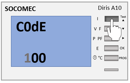
Press the ^ button. Then, 100 is displayed.
-
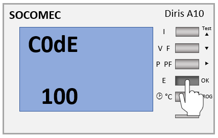
Press the OK button to confirm the entry.
6.2. Input — Measurement method
The following steps describe the procedure for configuring the measurement method.
-
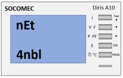
After entering the password, the menu item "nEt" appears with the value "4nbl".
-
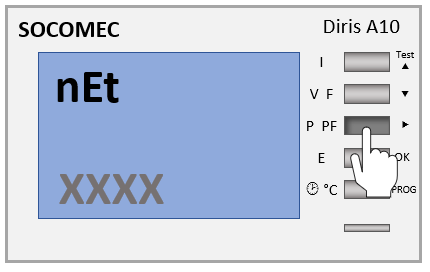
If "4nbl" is not set, press the ⇒ button. The selection then flashes.
-
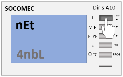
Press the ^ button several times until "4nbl" appears.
-
Press the OK button to confirm the entry.

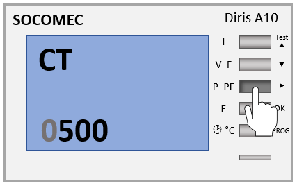
6.3. Input — Measuring transformer — Current ratio
The following steps describe the procedure for configuring the measuring transformer current ratio.
-
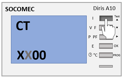
Press ^. Then, the menu item "CT" appears.
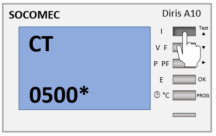
The transformer ratio is displayed in the form XXXX/5. You can read the transformer ratio on site (e. g. on the type label)
-
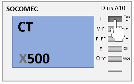
Press the ⇒ button. Then, the first digit flashes.
-
Press the ^ button several times until the desired value is displayed.
-
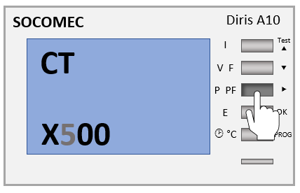
Press the ⇒ button. Then, the next digit flashes.
-
Press the ^ button several times until the desired value is displayed.
-
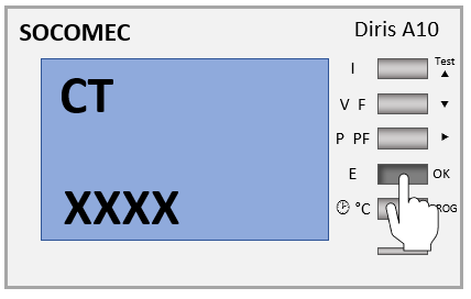
Carry out the above steps until the desired value is set.
-
Press the OK button to confirm the entry.
6.4. Input RS485 Modbus address
The following steps describe the procedure for configuring the RS485 Modbus addresses.
-
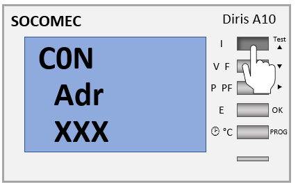
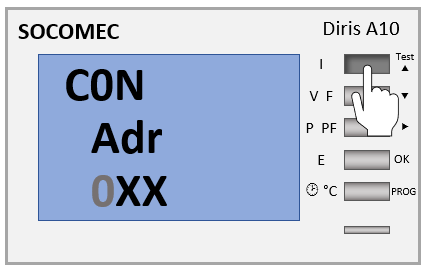
Press the ^ button several times until the menu item "C0N Adr" appears.
-
Press the ⇒ button. Then, the first digit flashes.
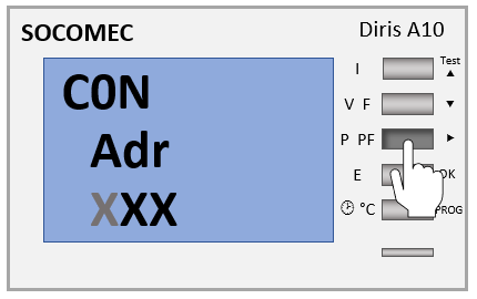
-
Press the ^ button several times until the desired value is displayed.
-
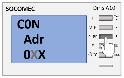
Press the ⇒ button. Then, the next digit flashes.
-
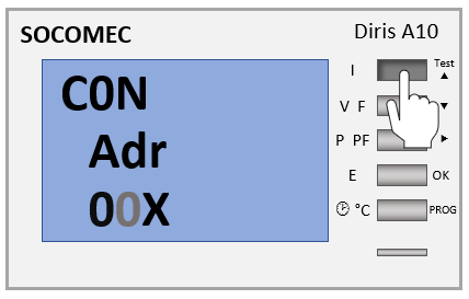
Press the ^ button several times until the desired value is displayed.
-
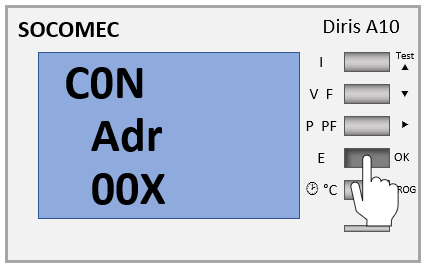
Carry out the above steps until the desired value is set.
-
Press the OK button to confirm the entry.
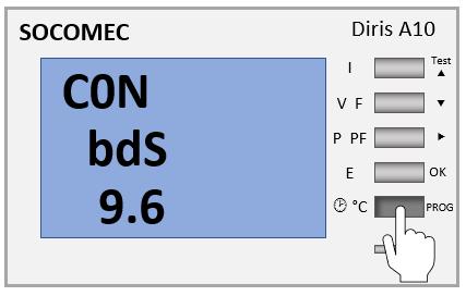
6.5. Communication speed input (baud rate)
The following steps describe the procedure for configuring the baud rate.
-
Press the ^ button several times until the menu item "CON bdS" appears.
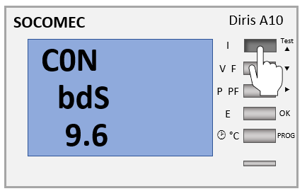
-
Press the ⇒ button. Then, the first digit flashes.
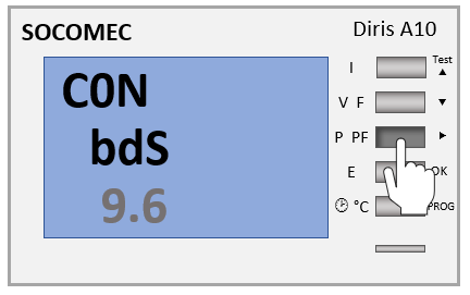
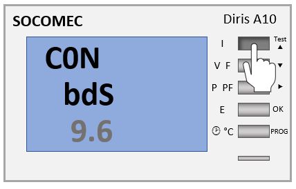
-
Press the ^ button several times until the value 9.6 is displayed
-
Press the OK button to confirm the entry.
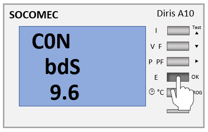
-
Press the PROG button to save the entries. The commissioning can then be continued.
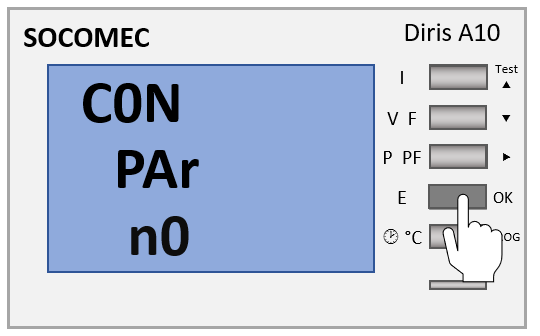
6.6. Communication parity input
The following steps describe the procedure for configuring the communication parity.
-
Press the ^ button several times until the menu item "CON PAr" appears.
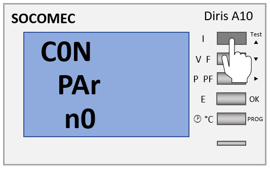
-
If the value "n0" is not selected, press the ⇒ button. The selection then flashes.
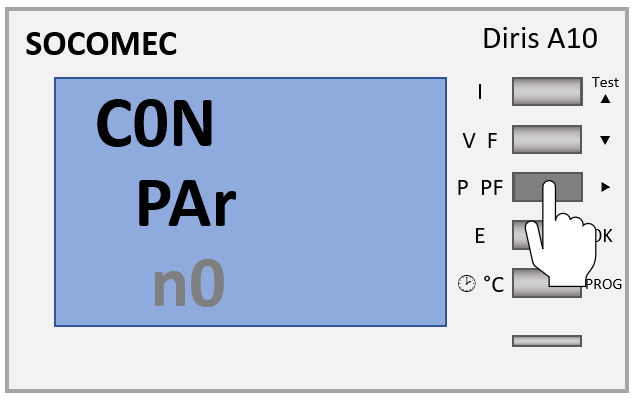
-
Press the ^ button until the value "n0" is displayed
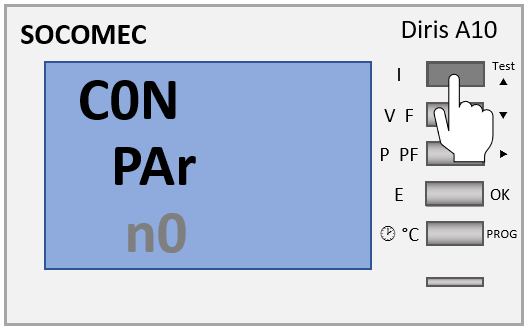
-
Press the OK button to confirm the entry.
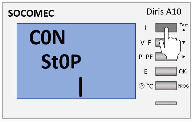
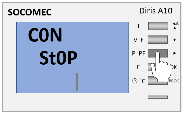
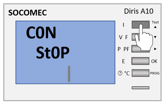
6.7. Communication stop bit input
The following steps describe the procedure for configuring the communication stop bit
-
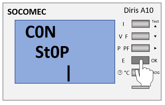
Press the ^ button several times until the menu item "CON St0P" appears.
-
If the value "1" is not selected, press the ⇒ button. The selection then flashes.
-
Press the ^ button until the value "1" is displayed
-
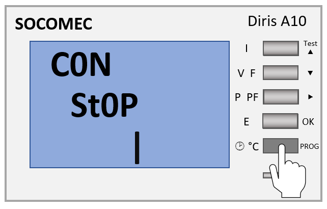
Press the OK button to confirm the entry.
-
Press the PROG button to save the entries. The commissioning can then be continued.
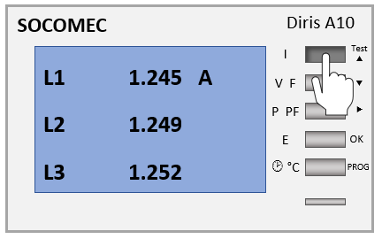
7. Connection — Function test
During the test, the meter must apply current and voltage to each of the three phases. Furthermore, this function assumes that the Power Factor of the installation is between 0.6 < PF < 1. If the Power Factor of the installation is not within this range, this function cannot be used.
With 4 BL / 3 BL / 2BL / 1 BL, only the TI connection is tested. With 4NBL and 3NBL, the entire connection is tested.
There are 7 different error codes:
-
Err 0 = no error
-
Err 1 = Phase 1 of the current transformer inverted
-
Err 2 = Phase 2 of the current transformer inverted
-
Err 3 = Phase 3 of the current transformer inverted
-
Err 4 = Voltage between V1 and V2 inverted
-
Err 5 = Voltage between V2 and V3 inverted
-
Err 6 = Voltage between V3 and V1 inverted
For errors Err 1, Err 2 and Err 3, the change can be made via the meter or manually by correcting the power connections. For errors Err 4, Err 5 and Err 6, the change must be made manually by correcting the voltage connection.
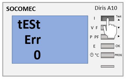
7.1. Example 1: Error "Err 0"
-
Press the TEST button for 3 seconds.
-
Error "Err 0" appears.
-
Press the TEST button for 3 seconds to exit test mode.
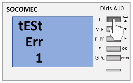
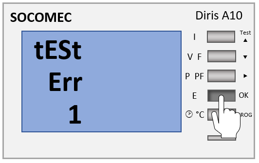
7.2. Example 2: Error "Err 1"
-
Press the TEST button for 3 seconds.
-
Error "Err 1" appears.
-
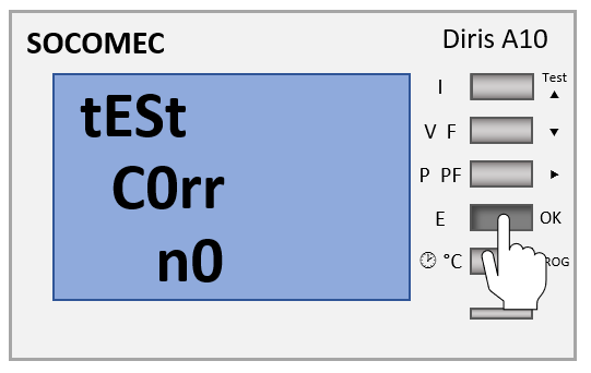
Press the OK button. The troubleshooting screen then appears.
-
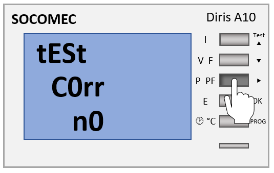
Press the ⇒ button.
-
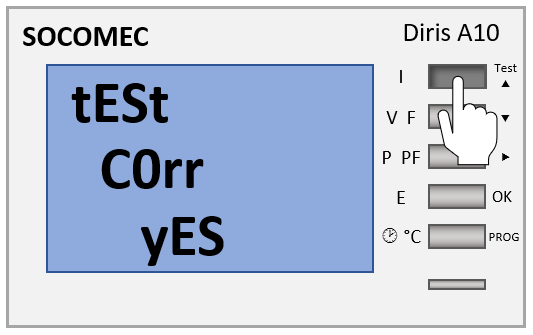
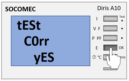
Press the TEST button. The error correction is set to "YES".
-
Press the OK button to confirm the entry.
-
Press the TEST button for 3 seconds to exit test mode.
7.3. Second test run
|
-
Press and hold the TEST button for 3 seconds.
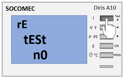
-
Press the OK button.
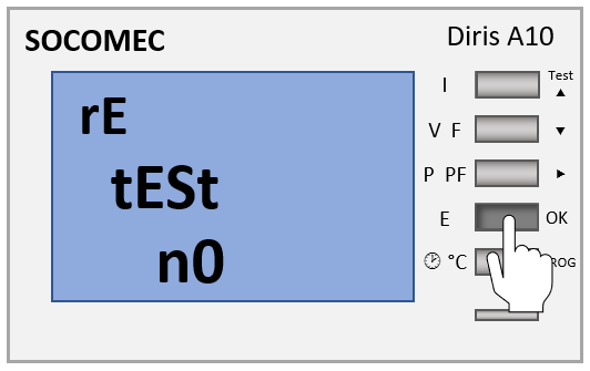
-
Press the TEST button. "YES" is displayed.
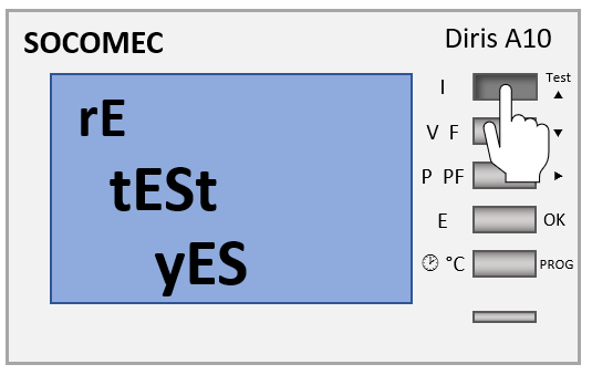
-
Press the OK button. As the changes from the first test are not taken into account, an error may be displayed again.
The configuration is now complete.