Installation and Configuration Manual — FEMS Package 3-Phase Sensor 80 A (SOCOMEC COUNTIS E23/E24)
1. Introduction
1.1. Legal provisions
Unless stated otherwise, the information contained in these documents is the property of FENECON GmbH. Publication, in whole or in part, requires the written consent of FENECON GmbH.
Diese Anleitung stellt keinen Anspruch auf Vollständigkeit und Korrektheit dar. Sie dient lediglich als Kurzfassung der originalen Anleitung von SOCOMEC. Diese finden Sie hier .
Subject to changes and printing errors!
1.2. Qualification of the installer
A qualified installer is a person who has the following experience and training:
-
Setting up, switching on, switching off, disconnecting, earthing, short-circuiting and repairing circuits and devices
-
Standard maintenance and use of protective devices in accordance with current safety standards
-
First aid/emergency care
-
Current knowledge of local regulations, standards and guidelines
2. Product description
2.1. Scope of delivery
After you have received the delivery, check that all components have been included. Inspect the scope of delivery for damage. If anything is missing or damaged, please contact the supplier immediately. The following components are included in the delivery:
-
SOCOMEC COUNTIS E23/E24 3-phase sensor
-
EasySync adapter RS-485 (optional)
-
Installation and configuration instructions for FEMS package 3-phase sensor 80 A
-
Montageanleitung für SOCOMEC COUNTIS E23/E24 (hier )
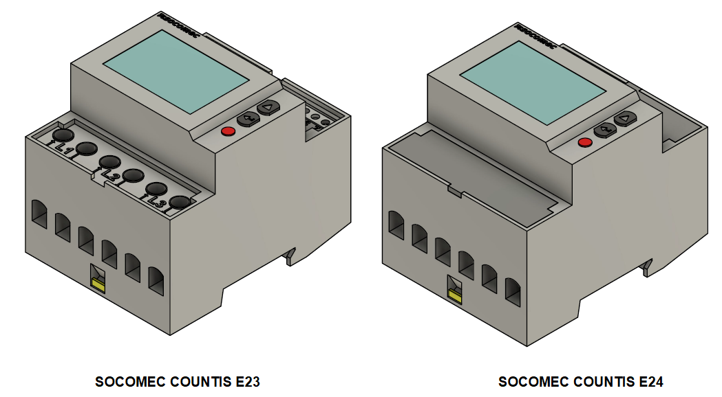
2.2. Model overview
COUNTIS E23 and E24 are modular active and reactive energy meters that count and display the energy consumed. They are designed for three-phase grids and allow direct connection up to 80 A. They are equipped with a MODBUS communication bus. The COUNTIS E23 and E24 are identical in construction. The E24 is the MID version of the E23.
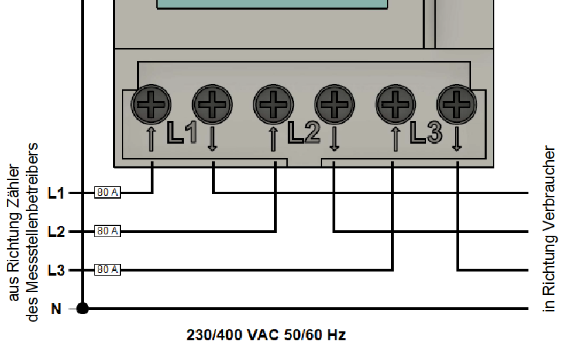
3. Connection
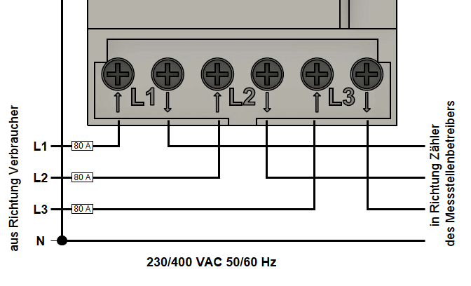
The meter is electrically connected through the 3 phases and the neutral conductor in accordance with the original instructions. The meter has an input and output for connecting the phases. If these are connected incorrectly, the meter may later output a negative value in Online Monitoring.
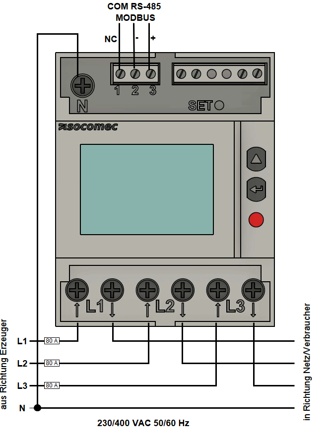
4. Communication
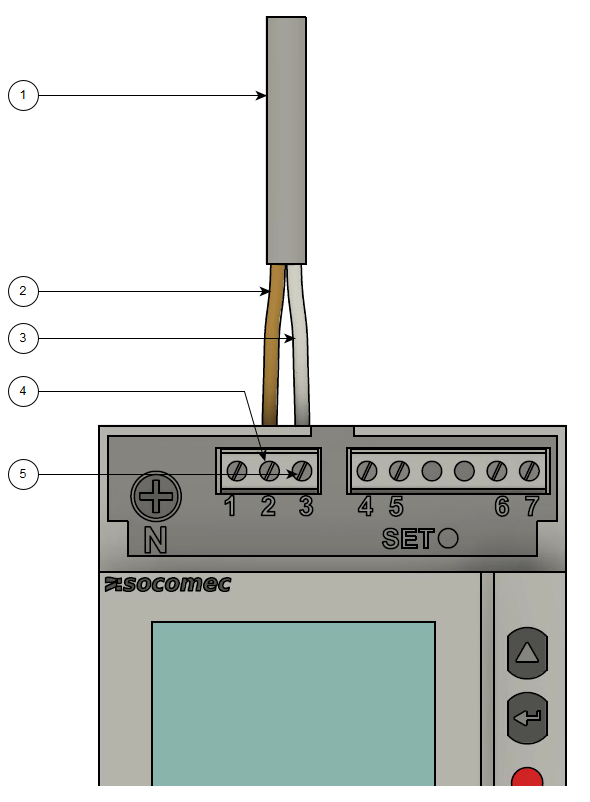
The Modbus communication available with COUNTIS E23/E24 takes place via a serial RS485 interface (2 or 3 wire), which enables the device to be operated from FEMS. In the standard configuration, 32 devices can be connected to a PC or a controller over 1200 meters using an RS485 interface.
-
COM RS-485 connection from FEMS
-
Data conductor minus (-) (B conductor)
-
Data conductor plus (+) (A conductor)
-
Minus (-) contact
-
Plus (+) Contact
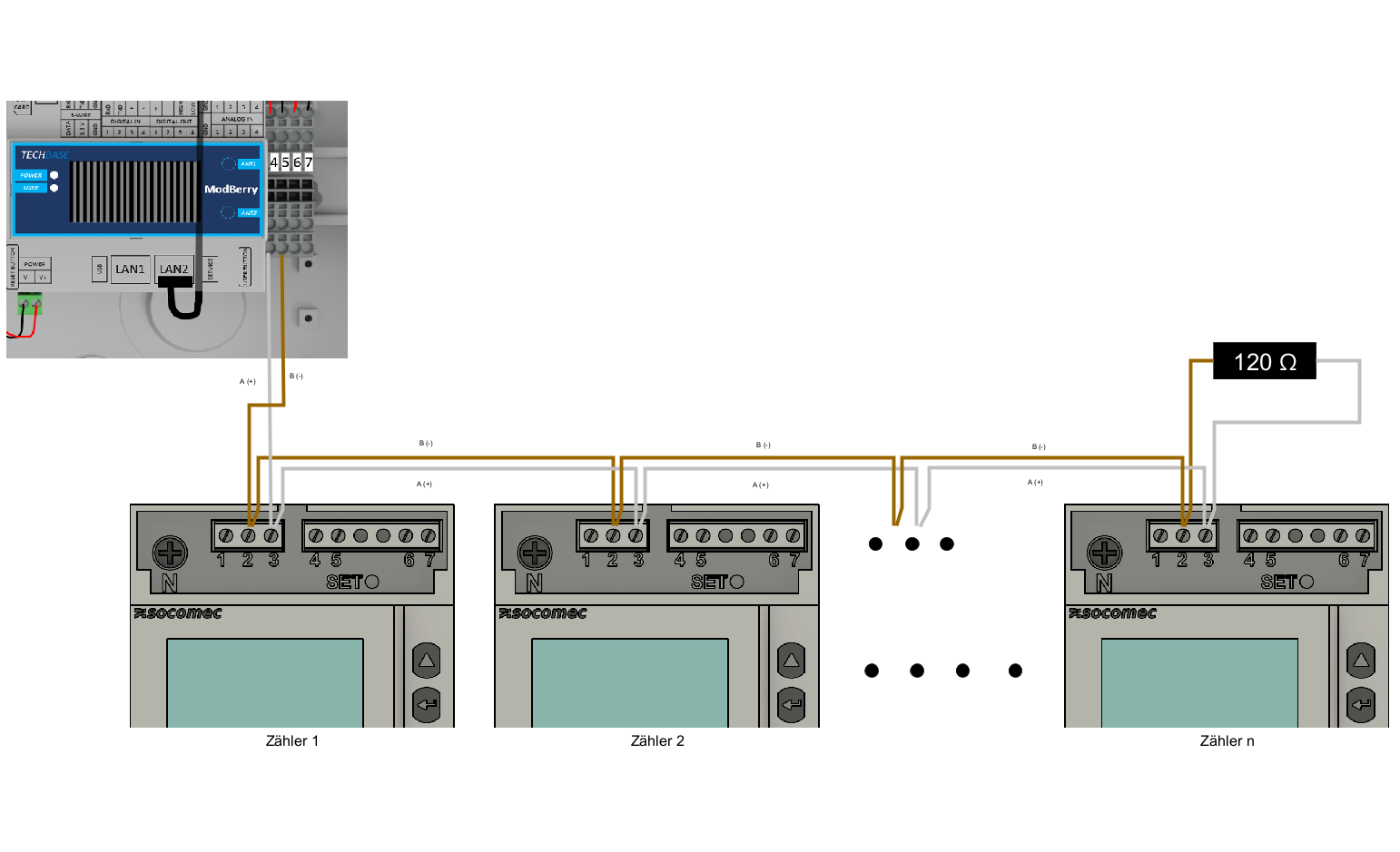
To connect several meters in series, the RS-485 connection must be looped through, as shown in the figure below.
Note the connection of the terminating resistor (120 Ω)!
|
If the supplied RS485 cable is not long enough, we recommend using a LiYCY with a cross-section of 0.5 mm². This is suitable for max. 500 m. In general, the manufacturer’s specifications and recommendations must be observed. |
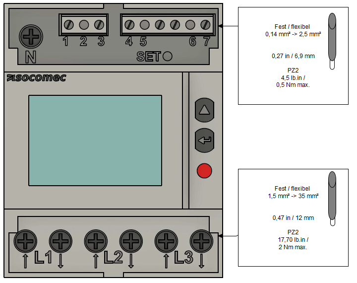
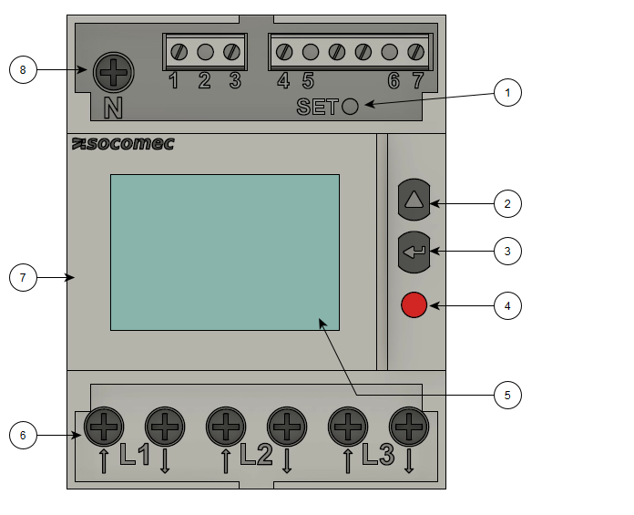
5. Overview of controls
-
SET button
-
Cursor key UP (^)
-
ENTER button
-
LED operating control
-
LCD screen
-
Three-phase network connection
-
Details of MID certification (if available)
-
Neutral conductor connection
6. Configuration
The following configuration settings must be used for use with FEMS:
| Baud rate for communication |
9.6 |
| RS-485 Modbus address — Grid connection point |
005 |
| RS-485 Modbus address — PV generation |
006 |
| RS-485 Modbus address — Other generators/consumers |
007…246 |
|
Follow the installation and service instructions for the meter installed to make the settings. The following steps are for simplification purposes only. |
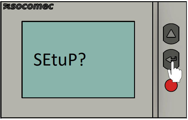
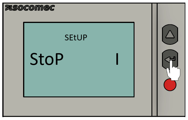
6.1. Opening the programming mode
-
Press the ENTER button to switch between the menu items within the configuration menu until the SETUP menu item appears.

-
Then press and hold the ENTER button for three seconds to enter programming mode.
6.2. Input — RS-485 Modbus address (Addr)
The following steps describe the procedure for configuring the RS-485 Modbus address.
-
Press the ^ button until the menu for setting the address appears
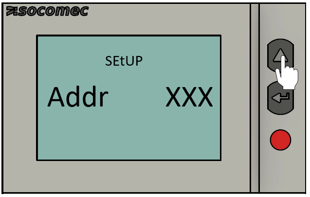
-
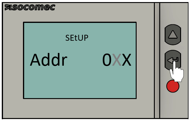
Press the ENTER button. The left-hand digit then flashes
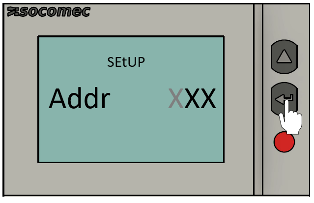
-
Press the ^ button until the value of the left-hand digit is set to 0.
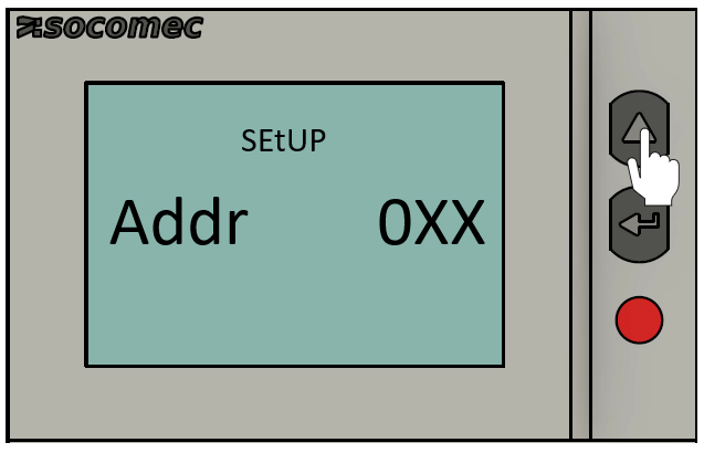
-
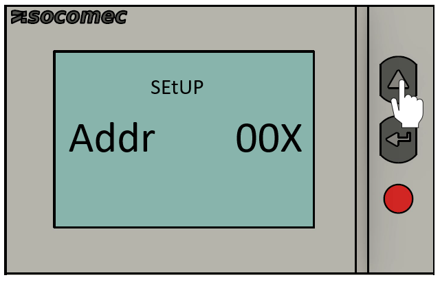
Press the ENTER button. The middle digit then flashes.
-
Press the ^ button until the value of the middle digit is set to 0.
-
Press the ENTER button. The right-hand digit then flashes.
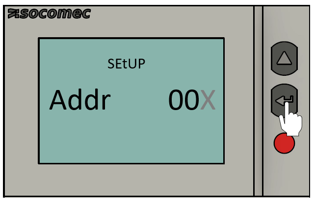
-
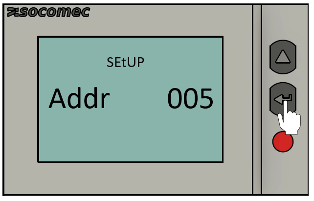
Press the ^ button until the value of the right-hand digit is set to 5.

-
Press the ENTER button to save the entries.
6.3. Communication speed (baud rate)
The following steps describe the procedure for configuring the baud rate.
-
Press the ^ button. The menu item for setting the baud rate appears.
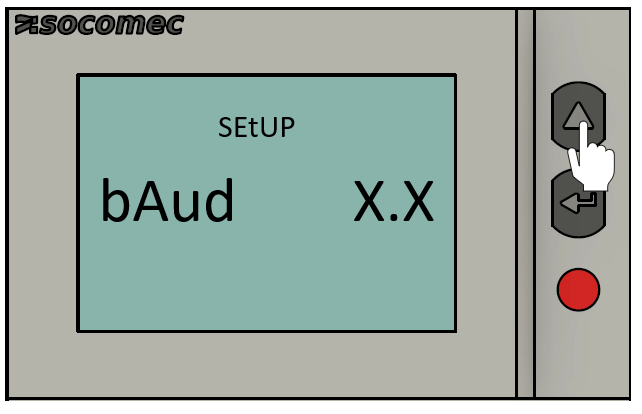
-
Press the ENTER button. The baud rate value then flashes.
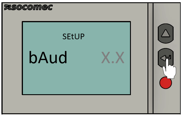
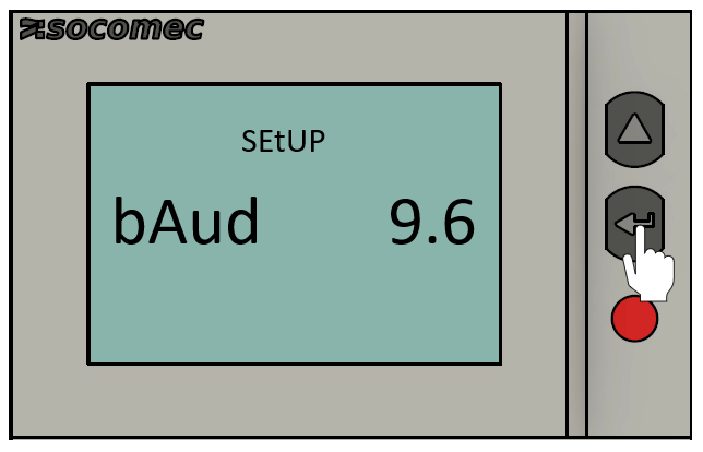
-
Press the ^ button to switch between the different baud rate values. Select the value 9.6.

-
Press the ENTER button to save the entry.
6.4. Communication parity
The following steps describe the procedure for configuring the communication parity.
-
Press the ^ button. The menu item for setting the communication parity appears.
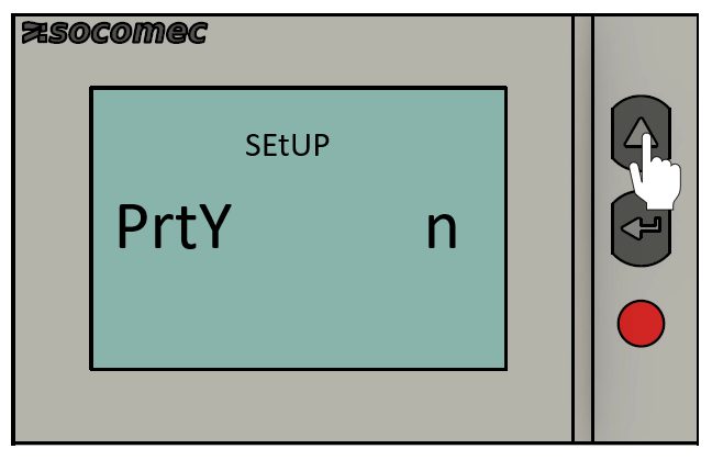
-
Press the ENTER button. The communication parity value then flashes.
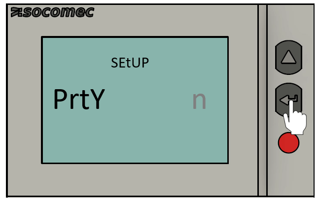
-
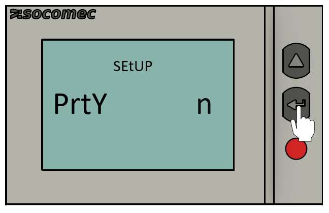
Press the ^ button to switch between the different values. Select the value n (none).
-
Press the ENTER button to save the entry.
6.5. Communication stop bit
The following steps describe the procedure for configuring the communication stop bit.
-
Press the ^ button. The menu item for setting the communication stop bit appears.
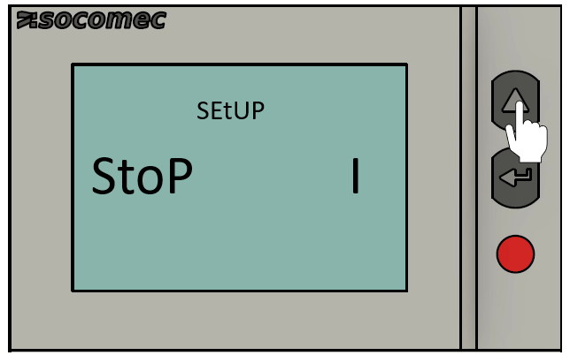
-
Press the ENTER button. The communication parity value then flashes.
-
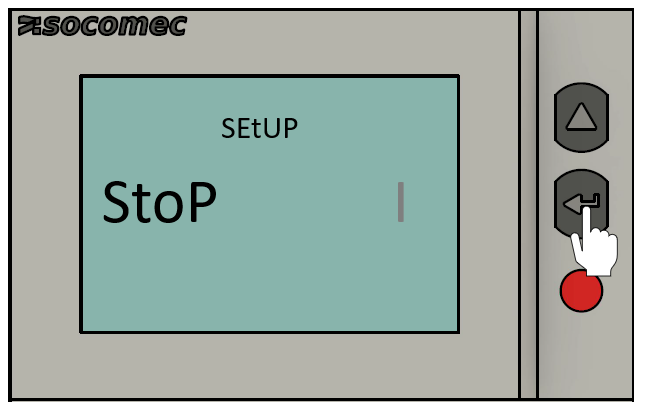
Press the ^ button to switch between the different values. Select the value 1.
-
Press the ENTER button to save the entry.
6.6. Exiting programming mode
-
Press and hold the ENTER button for three seconds. The "SAVE" menu then flashes with the value "y" (YES). This means that the entries will be saved. If you want to discard the entries, press the ^ button to go to the value "n" (NO)
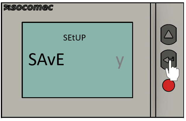
-
Press the ENTER button to confirm the entry.

The configuration of the meter is now complete. Proceed in the same way to configure other meters. Please note the different RS485 Modbus addresses.
7. Diagnostic messages
The following diagnostic messages are displayed if there are connection errors or faults
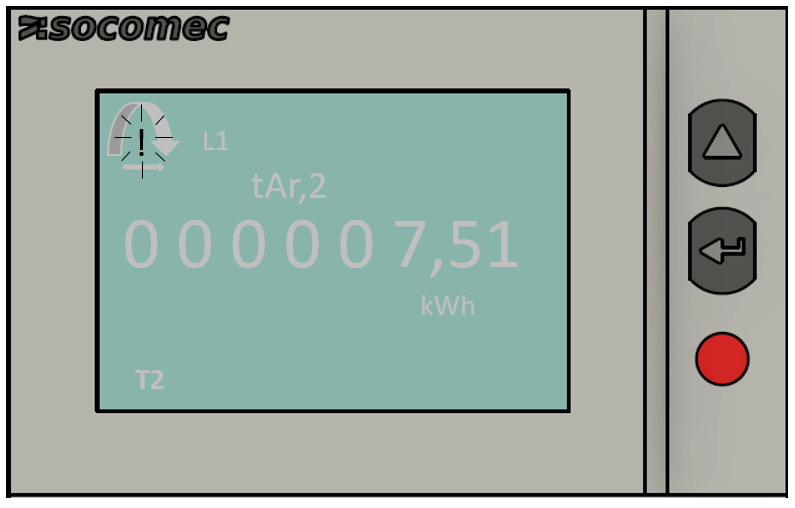
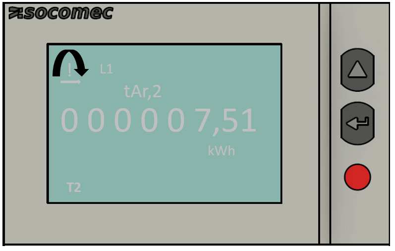
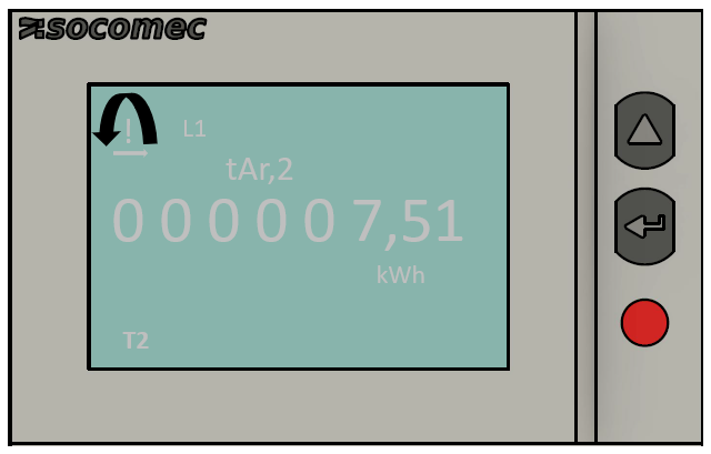
7.1. Missing phases
If one or more phases are not recognized, the exclamation mark flashes at the top left of the display.
8. Troubleshooting
Causes |
Solutions |
Device switched off |
Check neutral conductor and phase 1 cable connections |
Phases not shown on the display |
Check connections |
Phases reversed on the display |
Check network configuration |
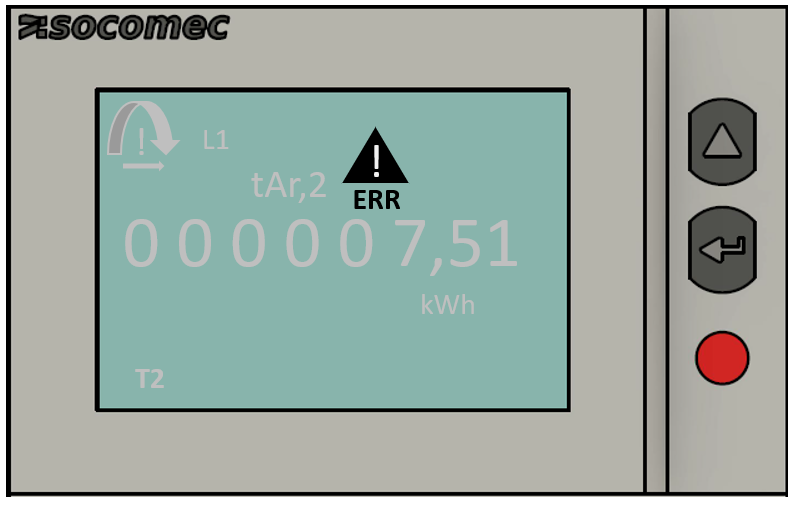
Error message |
Check whether meter is working properly |
The configuration is now complete.