Installation and Configuration Manual — FEMS Package 3-Phase Sensor without Current Transformer (KDK 2PU CT)
1. Introduction
1.1. Legal provisions
Unless stated otherwise, the information contained in these documents is the property of FENECON GmbH. Publication, in whole or in part, requires the written consent of FENECON GmbH.
These instructions do not claim to be complete or correct. It merely serves as an abridged version of the original instructions from KDK Dornscheidt.
Subject to changes and printing errors!
1.2. Qualification of the installer
A qualified installer is a person who has the following experience and training:
-
Setting up, switching on, switching off, disconnecting, earthing, short-circuiting and repairing circuits and devices
-
Standard maintenance and use of protective devices in accordance with current safety standards
-
First aid/emergency care
-
Current knowledge of local regulations, standards and guidelines
2. Product description
2.1. Scope of delivery
After you have received the delivery, check that all components have been included. Inspect the scope of delivery for damage. If anything is missing or damaged, please contact the supplier immediately. The following components are included in the delivery:
-
KDK Dornscheidt 2PU CT
-
Installation and configuration instructions for FEMS Package 3-Phase Sensor without Current Transformer (KDK 2PU CT)
-
Installation instructions for KDK Dornscheidt 2PU CT (Online: https://www.kdk-dornscheidt.de/wp-content/uploads/2021/08/KDK-Bedienungsanleitung_420565PRO20-U_4PU_052021V1.00.pdf)
2.2. Prerequisites
The following is required for using the 3-phase sensor:
-
Current transformer
|
Please note! The current transformers are not included in the scope of delivery! (Online: https://www.kdk-dornscheidt.de/produktkategorie/wandler/) Using the KDK meter as an example, the transformer ratio is 1 or 5. You can read the transformer ratio on the current transformers installed on site (see e. g. type label). |
-
FENECON Energy Management System (FEMS)
FEMS is being developed as an open source project under the name "OpenEMS" together with many other companies and institutes in the "OpenEMS Assocation e.V.". More information:
FEMS App: https://www.fenecon.com/fems-apps/
OpenEMS: https://www.openems.io
FEMS is a product component of the integrated FENECON power storage systems and other product combinations of battery inverters and batteries. More information can be found at https://fenecon.de/.
2.3. Model overview
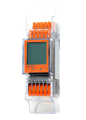
The KDK meter is a modular active and reactive energy meter that can count and display the energy consumed. It is designed for three-phase grids and must be operated with current transformers. The meter is equipped with a MODBUS communication bus.
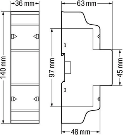
Height without cover |
97 mm |
Height w. cover |
140 mm |
Width |
36 mm |
Depth |
63 mm |
Weight (net) |
0.2 kg |
3. Connection
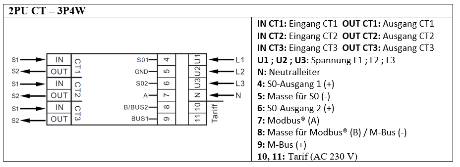
3.1. Terminal designation
The push-in technique can be used for solid conductors, fine-stranded conductors and fine-stranded conductors with wire ferrule. For fine-stranded conductors, the levers must be opened for connection.
Cross-section of the connection terminals:
- Single-wire conductors
-
0.2 … 4 mm2/24 … 12 AWG
- Fine-stranded conductors
-
0.2 … 4 mm2/24 … 12 AWG
- Fine-stranded conductors with wire ferrule and plastic collar
-
0.25 … 2.5 mm2
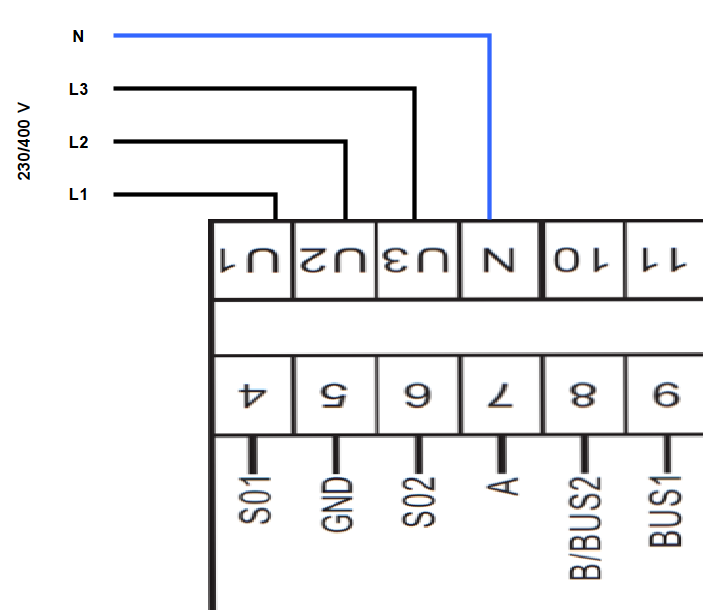
3.2. Voltage tap
The meter is electrically connected through the three phases and the neutral conductor in accordance with the original instructions. As this type of meter can only work with external current measurement sensors, this is a voltage tap of the three phases and the neutral conductor.
Auxiliary table for dimensioning the secondary cables for transformers with 5 A secondary current (XXXX/5A)
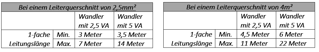
|
3.3. Connection of current transformers to the meter of the metering point operator
The current transformers must be connected to the meter of the metering point operator as shown below:
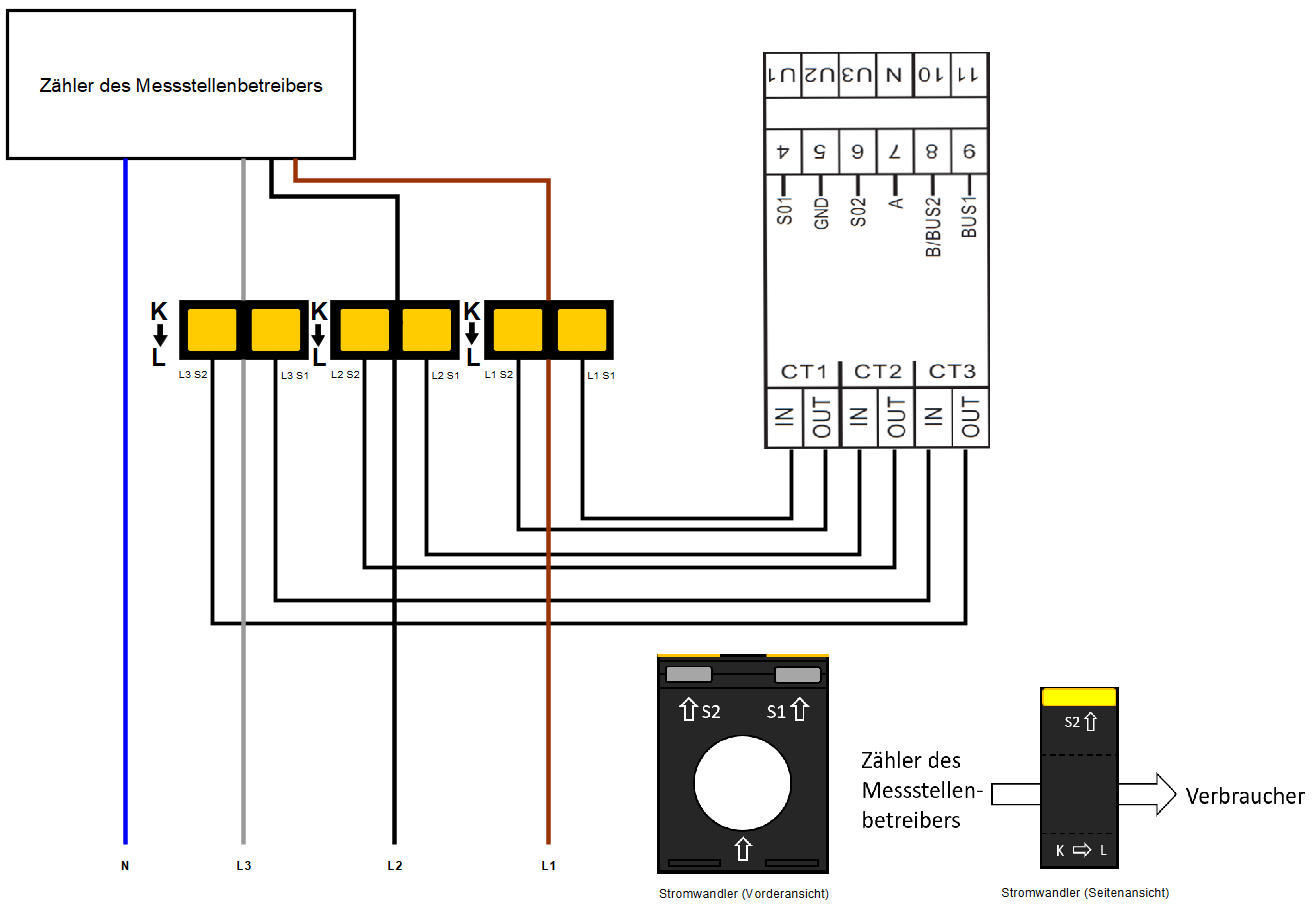
|
Ensure that the transformers are aligned correctly from K to L! |
3.4. Connection of current transformer to generator
The current transformers must be connected to the generator (inverter) as shown below:
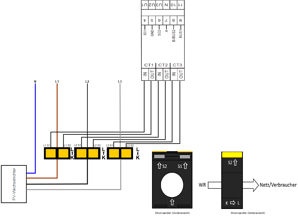
|
Ensure that the transformers are aligned correctly from K to L! |
3.5. Connection of current transformer to consumer load(s)
The current transformers must be connected to a consumer load as shown below:
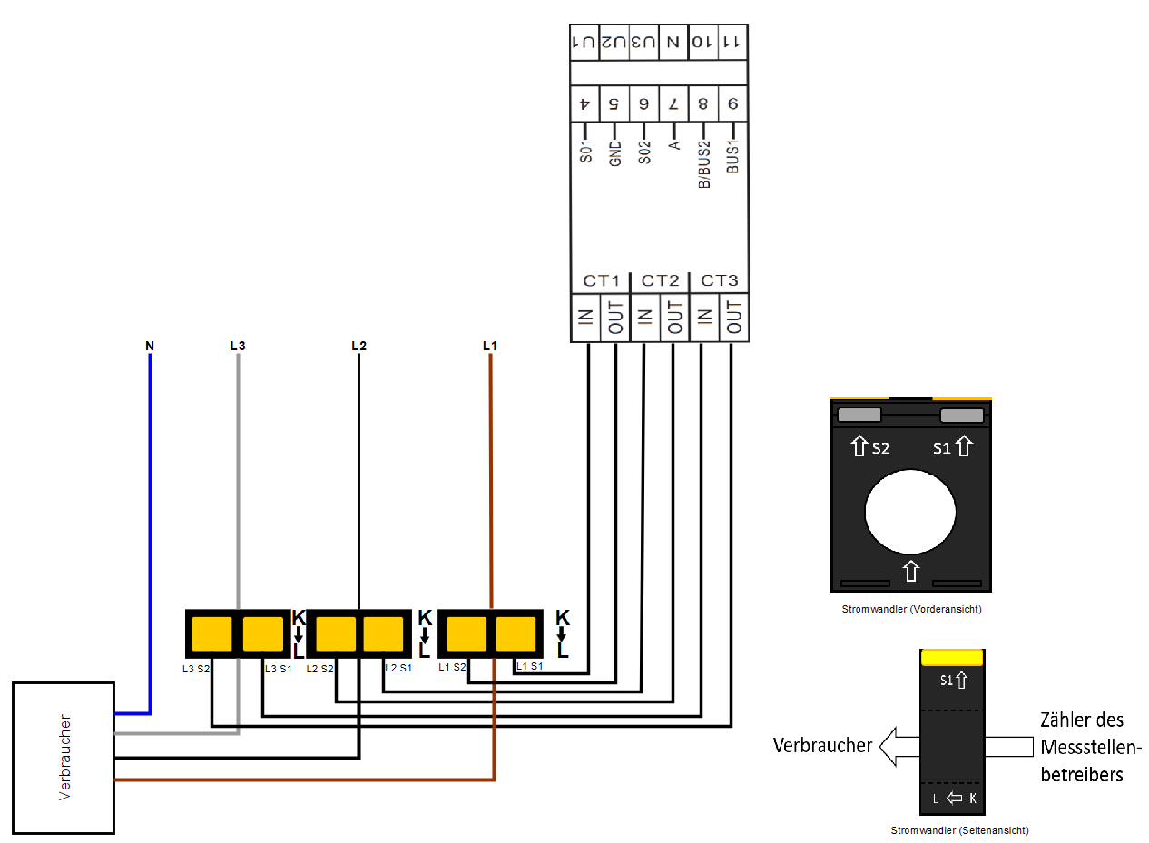
|
4. Communication
The Modbus communication available with the 2PU CT takes place via a serial RS485 interface (2 or 3 wire), which enables the device to be operated from the FEMS. In the standard configuration, 64 devices can be connected to a PC or a controller over 1000 meters with one RS485 interface.
The connections for Modbus communication are located above the meter, in the front row of terminals.

-
COM RS-485 connection from the FEMS direction
-
Data conductor Positive (+) (A conductor)
-
Data conductor Negative (-) (B conductor)
-
Minus (-) contact
-
Plus (+) Contact
To connect several meters in series, the RS-485 connection must be looped through, as shown in the figure below.
Note the connection of the terminating resistor (120 Ω/0.25 W)!
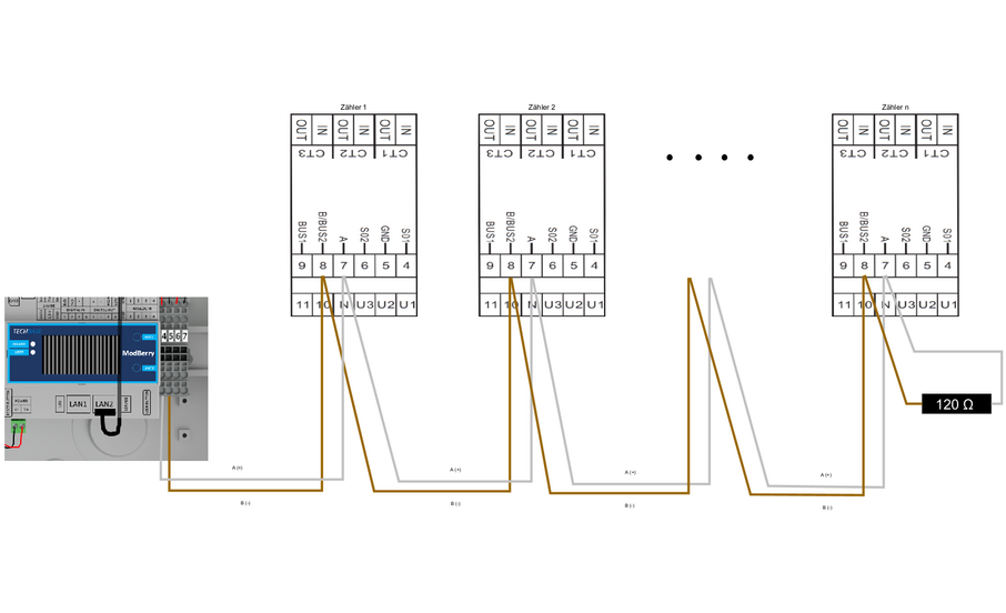
|
If the supplied RS485 cable is not long enough, we recommend using a LiYCY with a cross-section of 0.5 mm2. This is suitable for max. 500 m. In general, the manufacturer’s specifications and recommendations must be observed. |
5. Overview of controls
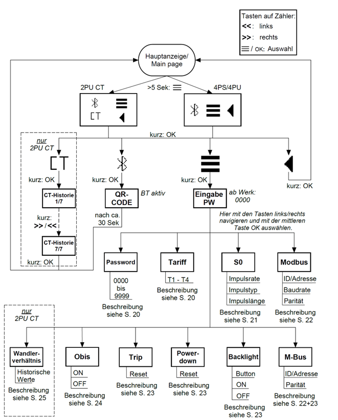
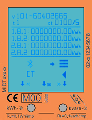
There are three buttons on the front of the meters, marked with a line. To access the menu, press and hold the middle button for ≥ 5 seconds.
The following display appears:
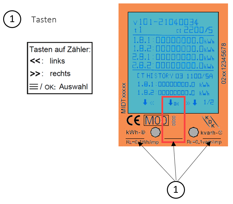
Here you have the option of activating the meter’s Bluetooth, on the far left in the picture. The symbol in the middle, three dashes, takes you to the actual menu where you can make adjustments to the meter settings. The arrow to the left, on the right in the picture, takes you back to the measured values.
6. Adjust configuration via buttons on the meter
6.1. Configuration parameters
The following configuration settings must be used for use with FEMS:
| Measuring transformer current ratio |
…/5 e. g. 500/5 = 500 A. |
| RS485 Modbus address grid connection point |
005 |
| RS485 Modbus address PV generation |
006 |
| RS485 Modbus address — other generators/consumers |
007…246 |
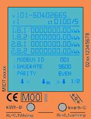
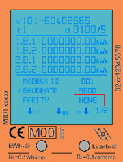
| Baud rate for communication |
9600 |
| Parity |
None |
The symbol in the display, with three dashes, takes you to the actual menu where you can make adjustments to the counter settings. The arrow to the left, on the right in the picture, takes you back to the measured values.
|
|

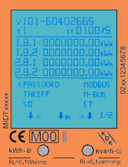
6.2. Password input
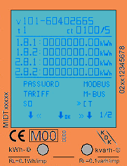
The settings can be made using the sensitive push-buttons on the front of the meter. Use the left and right buttons to scroll through the options. Confirm the setting with the middle button. Select the menu symbol (3 horizontal lines) to access the settings menu:
To access the settings menu, enter the 4-digit password (factory set to 0000). Confirm each digit (0-9) by pressing the middle button:

Once the password has been entered correctly, the settings menu appears:

6.3. Input — Measuring transformer — Current ratio
The following steps describe the procedure for configuring the measuring transformer current ratio.
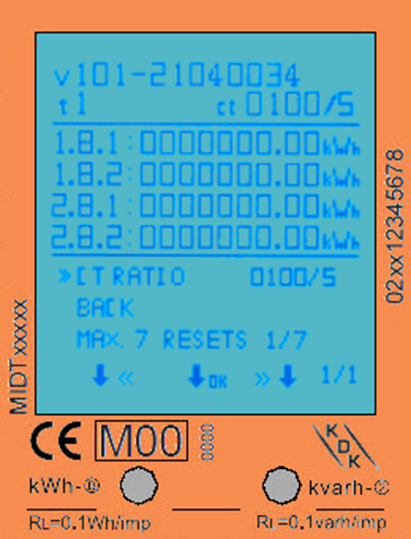
The primary current can be set to 0001 - 9999 A (with a secondary current of 1A) or 0005 - 9995 A (with a secondary current of 5 A). The secondary current can be set to /1A or /5A. A transformer ratio of CT=5/5A is preset at the factory.
You can store the transformer ratio under the CT menu item.
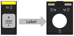
The transformer ratio (CT RATION) is displayed in the form XXXX/5 or XXX/1. You can read the CT ratio on site (e. g. on the type label).
|
|
6.4. Input RS485 Modbus address
To do this, use the sensitive touch buttons to go to the settings menu and select Modbus.
Then navigate to Modbus ID and press the middle button; you can now use the right and left buttons to lock the values. When the desired Modbus address is displayed, press the middle button to confirm it.
The factory-set Modbus address is 001.
The following addresses are required for communication.
- RS485 Modbus address grid connection point
-
005
- RS485 Modbus address PV generation
-
006
- RS485 Modbus address — other generators/consumers
-
007…246

|
|
6.5. Communication speed input (baud rate)
To do this, use the sensitive touch buttons to go to the settings menu and select Modbus.
Then navigate to Baud rate and press the middle button; you can now use the right and left buttons to lock the values. When the desired baud rate is displayed, press the middle button to confirm it.
The factory-set Modbus® baud rate is 9600 Bd. Please check the baud rate.
- Baud rate for communication
-
9600
|
|
|
6.6. Communication parity input
To do this, use the sensitive touch buttons to go to the settings menu and select Modbus.
Then navigate to Parity and press the middle button; you can now use the right and left buttons to adjust the setting. When the desired parity is displayed, press the middle button to confirm.
| The factory-set parity is EVEN. This must be changed to NONE. |
|
|
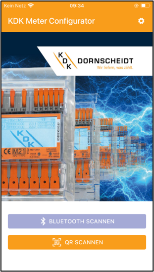
7. Bluetooth smartphone app
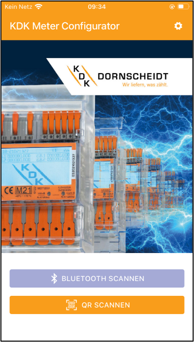
All Push-in-CAGE CLAMP® meters can be read and configured via Bluetooth®. The standard used is BLE 4.2. You can download the smartphone app for Android and iOS free of charge from the respective stores. The smartphone app can be found under the name KDK Meter Manager.

Below you will find a QR code for the explanatory video on how to activate Bluetooth and the options via the app:

7.1. Activating the BT interface on the meter
1. When the arrows >> point to the Bluetooth® symbol, briefly press the center button: |

|
2. The Bluetooth® interface of the meter is now activated and ready for communication with the KDK Meter Configurator App. To establish the connection with the meter, scan the QR code via the camera of your smartphone or browse the Bluetooth® environment by selecting the corresponding menu item in the app. |
|
3. When a Bluetooth® connection is established, the Bluetooth® symbol is shown at the top right of the display. |
|
7.2. Bluetooth connection with the meter
-
Start the smartphone app. The desired language can be set in the settings menu (cogwheel) at the top right of the display.
|
|
-
The energy meter can be connected with the Scan Bluetooth or Scan QR function.
-
Scan Bluetooth: The app scans for all Bluetooth measuring devices in the vicinity.
Select the correct serial number for the connection. -
Scan QR: The app opens the camera of the cell phone to scan the QR code on the meter display. As soon as the code has been scanned, the meter is connected.
-
7.3. App - device page
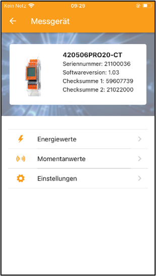
The energy meter is now connected to the smartphone app. The meter type, serial number, software version and checksums are displayed on the device page.
7.4. App - reading the meter data
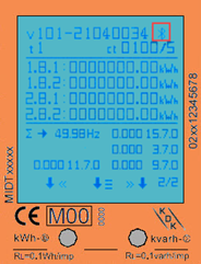
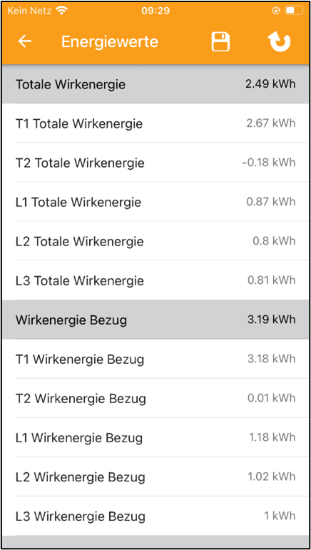
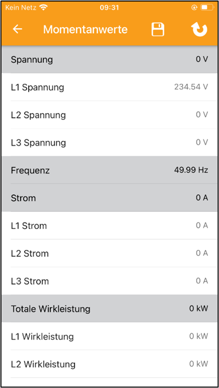
All energy values can be found under "Energy" and all instantaneous values under "Instantaneous".
Refresh the data using the refresh arrow in the top right-hand corner.
|
|
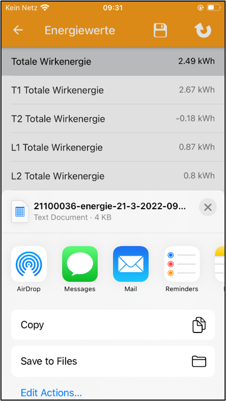
Save the data using the electrical energy storage icon in the top right-hand corner. The data can be saved locally on the smartphone or forwarded via various channels such as e-mail, Bluetooth or other programs.
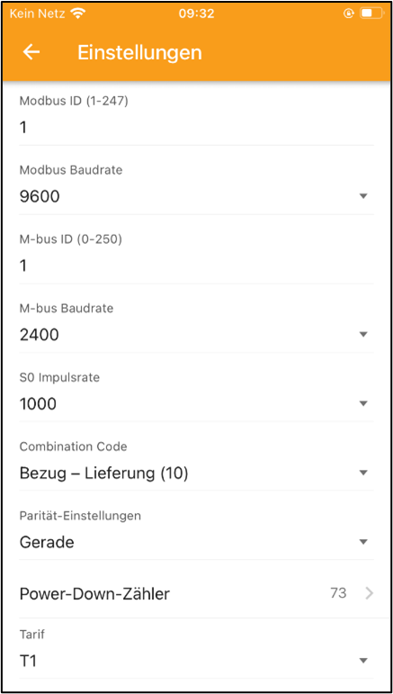
7.5. App - Changing meter parameters
Settings can be selected individually and/or saved all at once.
-
Select the settings you want to change. The changed settings are highlighted in green.
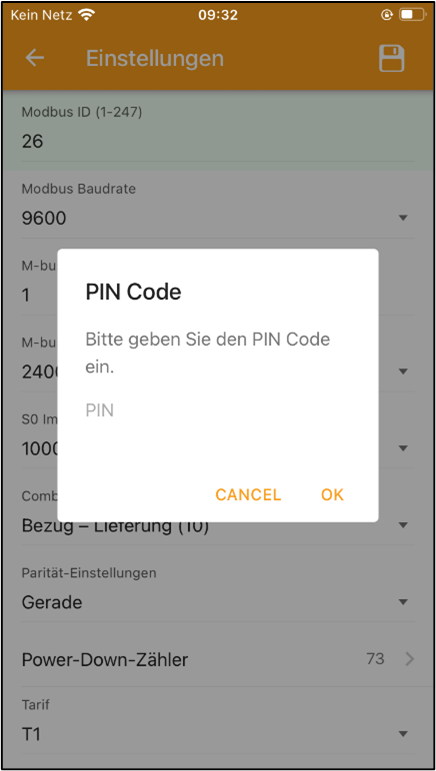
-
Save the values via the storage disk in the top right-hand corner.
-
A pop-up menu for the password appears first. By default, the password is always 0000.
-
The password can only be changed on the meter using the buttons. After entering the correct password, the new settings are saved in the meter.
|
|
The following configuration settings must be used for use with FEMS:
| Measuring transformer current ratio |
…/5 e. g. 500/5 = 500 A. |
| RS485 Modbus address grid connection point |
005 |
| RS485 Modbus address PV generation |
006 |
| RS485 Modbus address — other generators/consumers |
007…246 |
| Baud rate for communication |
9600 |
| Parity |
None |
8. Troubleshooting
Problem |
Possible cause |
Check/solution |
*The red consumption LED on the front is not flashing or the meter is not counting up. |
There is no load connected to the meter or the load on the line is very low. |
Connect a consumer load to the meter and use a measuring device e. g. ammeter to measure whether the load is present and the LED is flashing. |
The meter is not counting. |
No consumer load is connected to the meter. |
Check whether the red consumption LED is flashing. |
No pulse output. |
The pulse output is not supplied with DC voltage. The pulse output is not connected correctly. |
Use a voltmeter to check whether the external voltage source (Ui) is DC 5 - 27 V. Check whether the connection is correct: see section 6.6.3 S0 pulse output. |
If none of the above points have led to a solution, please contact technical support. Phone: 02244 / 91994-47 |
||
The configuration is now complete.