FENECON Industrial M — Assembly and Operating Instructions
1. General information
1.1. About these instructions
These installation and service instructions have been prepared in accordance with Directive 2014/35/EU. They enable the safe and efficient handling of the electrical equipment "ESS10 Container" (for the purpose of documentation described as "system").
These installation and service instructions are an integral part of the system and must be kept in its immediate vicinity and accessible to personnel at all times. Furthermore, all documents listed in the appendix to these installation and service instructions and the operating instructions of the component manufacturers must be observed!
Personnel must have carefully read and understood these installation and service instructions before starting any work.
1.2. Manufacturer
FENECON GmbH
Gewerbepark 6
94547 Iggensbach
Germany
Phone +49 (0) 9903 6280 0
Fax +49 (0) 9903 6280 909
E-mail: service@fenecon.de
Website: www.fenecon.de
1.3. Formal information on installation and service instructions
© FENECON GmbH, 2026.
All rights reserved.
Reprinting, even in part, is only permitted with the permission of FENECON GmbH.
1.4. Version/revision of the installation and service instructions
| Version/revision | Changes to installation and service instructions | Date | Name |
|---|---|---|---|
V0.1 |
Initial draft |
09/09/2020 |
CE Design |
V0.2 |
Initial draft |
03/11/2020 |
CE Design |
V0.3 |
Initial draft |
03/11/2020 |
CE Design |
V0.4 |
Publication on docs.fenecon.de |
20/03/2025 |
FENECON PM |
V0.5 |
Update RCD |
27/04/2026 |
FENECON PM |
1.5. Symbol conventions
| Image | Meaning |
|---|---|
"Highlighting" |
Highlighting of special terms in the text |
[Button] |
Operating and display element (e. g. push-button, signal light) |
>>Button<< |
Button and visualization (e. g. push-button, signal light) |
→ |
Reference to chapters/sections of these instructions or to Applicable documents (→ chapter Technical data) |
|
||
|
||
|
||
|
||
|
1.6. Structure of warning notices
Warning notices protect against possible personal injury and damage to property if observed and classify the magnitude of the danger by means of the signal word.
Warnings are structured according to the SAFE method:
| Signal word | Meaning |
|---|---|
S |
Signal word (DANGER, WARNING, CAUTION or NOTICE) |
A |
Aspects of danger |
F |
Foreseeable (consequences) |
E |
Escape |
|
Source of the danger
|
1.7. Terms and abbreviations
The following terms and abbreviations are used in the installation and service instructions:
| Term/abbreviation | Meaning |
|---|---|
AC |
Alternating Current |
Battery Pack |
Battery pack for installation in EVs. |
BCS |
Battery Control System |
BMS |
Battery Management System |
BSMU |
Battery Stack Management Unit — Management unit for battery stacks |
Connection Box |
It connects/disconnects pack low-voltage lines. It consists of main relay, pre-charge relay, current sensor, BMS power supply and CAN network for communication between the high order system and the BMS. |
EMS |
Energy Management System |
ESS |
Energy Storage System — Energy storage system |
FEMS |
FENECON Energy Management System |
module |
composition in which 16 cells are connected with 8 in series and 2 in parallel. Each battery pack consists of 12 modules connected in series. |
MS |
Medium voltage |
MSDS |
Material Safety Data Sheets |
NS |
Low Voltage |
NSHV |
Low-voltage main distribution board |
PCS |
Power Conversion System |
PV System |
Photovoltaic System |
RCD |
Residual Current Device — Residual current device |
RO |
Read Only |
SDSW |
Service Disconnection Switch |
WO |
Write Only |
1.8. Appendix to this document
All documents listed in the appendix to these installation and service instructions must be observed.
See Applicable documents.
1.9. Availability
The operator must keep these installation and service instructions or relevant parts of them within easy reach in the immediate vicinity of the product.
If the product is handed over to another person, the operator passes these installation and service instructions on to that person.
1.10. Scope of delivery
| List item | Component | Amount | Comment |
|---|---|---|---|
1 |
Container incl. cooling system, lockable |
1 |
includes key (1) |
2 |
NSHV incl. circuit breaker |
1 |
|
3 |
Control cabinet incl. FEMS and grid and plant protection |
1 |
|
4 |
Batteries, BMW; type: SE09, i3 |
depending on configured capacity |
High-voltage battery |
5 |
Inverter REFUstore 88k |
1 |
REFU Elektronik GmbH |
or |
|||
5 |
KACO gridsave 92.0 kVA |
depending on system configuration; |
KACO new energy GmbH |
6 |
Document folder |
1 |
Instructions, E-plan |
The equipment of the container depends on the ordered variant of the FENECON system.
The software licenses required to operate the system are not included in the scope of delivery. However, various FEMS applications are available for operation and can be installed both subsequently and directly during commissioning.
Scope of delivery — Optional
-
Aspirating smoke detector
2. Safety
2.1. Intended use
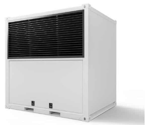
The FENECON Industrial M is an industrial energy storage system consisting of various modules. These include, in particular, efficient inverters, the FENECON energy management system (FEMS) and slide-in battery modules including BMS.
The energy storage system is used to store and supply electrical energy.
The system must only be used in compliance with the permissible technical data (section: Technical data).
2.2. Field of application
The product is intended exclusively for use in the following areas of application:
-
Industrial sector
Any other use is not in accordance with the intended use.
2.3. Qualification of staff
Qualified personnel must be deployed for the intended use, installation and maintenance of the system. The area of responsibility, competence and supervision of the personnel must be precisely regulated by the operator.
2.3.1. Maintenance personnel
Maintenance personnel include qualified electricians or persons who have completed comparable country-specific training and have the appropriate qualifications. Maintenance personnel are commissioned by the operator to maintain the system and have the following knowledge:
-
Functionality and maintenance points of the system.
-
Hazards on the system and suitable protective measures.
-
Cleaning, preserving, refilling or replacing operating materials (e. g. coolant).
-
Replacement of wearing parts.
-
Retrofitting and professional adjustment of the system.
2.3.2. Qualified electricians
Qualified electricians include persons who:
-
are able to carry out work on electrical systems due to their technical training, experience and knowledge of the relevant standards and regulations.
-
have been commissioned and trained by the operator to carry out work on electrical systems and equipment of the battery system.
-
are familiar with how the battery system works.
-
recognize hazards and prevent them by taking appropriate protective measures.
-
have access to all maintenance information.
2.3.3. Service staff
Service personnel includes: Manufacturer personnel or specialist personnel instructed and authorized by FENECON GmbH who must be requested by the operator for work on the electrical energy storage system (e. g. assembly, repair, maintenance, work on the batteries, etc.).
2.3.4. Qualified person
A qualified person is a person who has the necessary specialist knowledge to inspect work equipment (e. g. tools, devices, machines or systems) based on professional training, professional experience and recent professional activity. The person is not subject to any professional instructions in their inspection activities and must not be disadvantaged because of these activities.
2.4. Safety and protective devices
-
The safety devices must not be bypassed or switched off.
-
Operating the electrical energy storage system without or with defective protective devices is prohibited.
-
The safety equipment must always be kept within easy reach and checked regularly.
2.4.1. Overview
The following safety and protective devices are located on the system:
| Image | Safety/protective device |
|---|---|
|
Maintenance door — battery side, lockable |
|
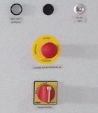
Emergency-off push-button (red button) on the control cabinet, acknowledgement key (button top left), as well as main switch (bottom) and LAN connection (top right) |
|
Earthing connections on the outer wall of the container (outside) |
|
Earthing connections inside the NSHV as a potential rail |
|
Lightning protection through the steel shell of the container |
|
Optional: smoke extraction/fire alarm system |
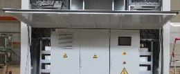
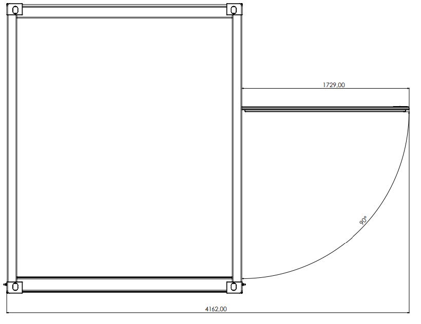
2.4.2. Maintenance door
Two maintenance doors are installed on the system (battery side and control cabinet side), which can be locked with the key supplied. During operation of the system, the maintenance doors are locked and prevent access to the system technology. The maintenance doors can be opened for maintenance and repair work. These open upwards to an angle of 90°. When opened, the maintenance door requires additional space of 1.73 m.
2.4.3. Emergency-off push-button
In emergency situations, the system can be switched off using the emergency-off push-button. The emergency-off push-button must not be used to switch the system off normally. The system is equipped with one emergency-off push-button.
The emergency-off push-button is located on the control cabinet inside the system.
Once the emergency situation has been rectified, the emergency-off push-button must be unlocked before the system is switched back on.
Pressing the emergency-off push-button
Pressing the emergency-off push-button triggers the following reactions:
-
12 V supply is switched off.
-
HV relays in the battery are disconnected.
-
The HV voltage to the outside to the inverters is switched off.
Unlocking the emergency-off push-button
The emergency-off push-button must be unlocked before switching back on after a tripped emergency-off:
-
Pulling out the emergency-off push-button
Confirm emergency stop
The emergency stop is confirmed using the emergency-off push-button on the front of the control cabinet.
2.5. Sheet steel for the discharge of lightning currents
Lightning protection is guaranteed by the container’s continuous material thickness of 4 mm.
2.6. Behavior in case of emergency
Immediate measures after an accident
The system and its surroundings are designed in such a way that accidents can be ruled out according to human judgment if:
-
all safety devices are active,
-
all safety regulations are complied with and
-
all maintenance and servicing work is carried out within the prescribed intervals.
Proceed as follows in emergency situations:
-
Press the emergency-off push-button.
-
Leave the zone of danger immediately.
-
Switch off the main switch with emergency stop function on the control cabinet.
-
Secure the zone of danger of the system.
-
Report to the system operator/responsible person.
-
Call a doctor if necessary.
2.7. Fire protection measures
Fire protection measures for the 10-foot industrial container:
Causes of fire
-
Spontaneous ignition of flammable materials such as oils, greases, paints and plastics that are exposed to radiant heat.
-
Welding in the immediate vicinity of flammable materials.
-
Contaminated smoke extraction systems.
-
Deposits in the ventilation ducts and on the filters.
-
Damaged, live cables.
-
Flammable operating fluids and coolants (increased fire risk).
Preventive measures
-
Do not store flammable materials in the container.
-
Only use flame-retardant operating fluids and coolants.
-
Clean extraction and ventilation systems regularly.
-
Change dirty filter elements.
-
Install suitable fire extinguishers in the container.
-
Train service personnel in firefighting.
Fire fighting
-
The use of carbon dioxide fire extinguishers is recommended for live components (control cabinets, control panels, etc.).
-
The battery packs must be sprayed with very large quantities of water until the fire is extinguished.
-
Keep an appropriate distance due to the possible formation of flames when burning electrolyte solution from the batteries.
-
Do not lead the fire hose directly into the battery packs.
-
Fully ventilate the container.
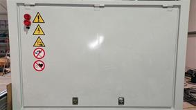
2.8. Pictograms
Pictograms on the system indicate dangers, prohibitions and instructions. Illegible or missing pictograms must be replaced by new ones.
| Piktogramm | Bedeutung | Position |
|---|---|---|

|
Warnung vor gefährlicher elektrischer Spannung |
Piktogramm am Gehäuse, und Kennzeichnung von Komponenten, bei denen nicht klar zu erkennen ist, dass sie elektrische Betriebsmittel enthalten, die Anlass für ein Risiko durch elektrischen Schlag sein können. |

|
Warnung vor ätzenden Stoffen |
Auf den Batteriemodulen |

|
Vor Benutzung erden |
Im Bereich der Erdungsanschlüsse (z. B. am Container) |

|
Getrennte Sammlung von Elektro- und Elektronikgeräten |
An den Batteriemodulen |

|
Warnung vor Handverletzungen |
|

|
Warnung vor heißer Oberfläche |
|

|
Allgemeines Warnzeichen |
|

|
Warnung vor Gefahren durch das Aufladen von Batterien |
|

|
Allgemeines Verbotszeichen |
|

|
Keine offene Flamme; Feuer, offene Zündquellen und Rauchen verboten |
|

|
Kein Zutritt für Personen mit Herzschrittmachern oder implantierten Defibrillatoren |
|

|
Zutritt für Unbefugte verboten |
|

|
Anleitung beachten |
|

|
Kopfschutz benutzen |
|

|
Fußschutz benutzen |
|

|
Handschutz benutzen |
2.9. Components and operating materials
2.9.1. Coolant
The coolant used in the integrated air conditioning unit is R134A.
Further information on the coolant R134A can be found in the corresponding manufacturer’s safety data sheet (appendix, Applicable documents).
2.9.2. Battery electrolytes
-
Electrolytes are used in the battery packs (lithium-ion polymer batteries).
-
The electrolyte solution in the batteries is a clear liquid and has a characteristic odor of organic solvents.
-
The electrolyte is a flammable solution.
-
The electrolyte in the battery packs is corrosive.
-
Contact with electrolyte solution can cause severe burns to the skin and damage to the eyes.
-
Do not inhale the vapors.
-
In case of ingestion, inhalation, contact with skin or eyes, rinse with plenty of water as soon as possible and contact a poison control center or doctor immediately.
Further information on the electrolyte solution can be found in the manufacturer’s safety data sheet (Appendix, Applicable documents).
2.10. Electrical equipment
-
Work on electrical equipment may only be carried out by qualified electricians.
-
The five safety rules must be observed for all work on electrical components:
-
Disconnect.
-
Secure against restarting.
-
Check that there is no voltage.
-
Ground and short-circuit.
-
Cover or shield neighboring live parts.
-
-
Maintenance work must only be carried out by trained specialist personnel.
-
Regularly carry out checks for insulation and container/housing damage.
-
The system must never be operated with faulty or non-operational electrical connections.
-
Always keep control cabinets locked. Only authorized personnel with appropriate training and safety instructions should be allowed access.
-
Switched off the system immediately in the event of faults in the power supply.
-
Observe the inspection and maintenance intervals for electrical components specified by the manufacturer.
-
Some equipment (e.g. inverters) with an electrical intermediate circuit can still carry dangerous residual voltages for a certain time after disconnection. Before starting work on these systems, the absence of voltage must be checked.
-
If the main switch is switched off, specially marked external circuits (e.g. for control cabinet lighting) may still be live!
2.11. Personal protective equipment
Depending on the work on the system, the following personal protective equipment must be worn:
-
Protective footwear.
-
Insulated protective gloves in accordance with DIN EN 60903 (for work in the HV range).
-
Protective eyewear.
-
Protective headgear.
2.12. Conversions or modifications
Unauthorized conversion or modification of the system is prohibited.
2.13. Spare and wear parts
The use of spare and wear parts from third-party manufacturers can lead to risks. Only original parts or spare and wear parts approved by the manufacturer must be used. The instructions for spare parts must be observed. Further information can be found in the spare parts list (Appendix, Applicable documents).
3. Technical data
3.1. General system
| Description | Details |
|---|---|
Ident. no. |
s. type label |
Intended service life |
15 years |
Year of manufacture |
from 2020 |
Battery technology |
lithium-ion |
Amount of batteries, max. |
16 |
Amount of inverters, max. |
8 |
Installation site |
Outdoor area |
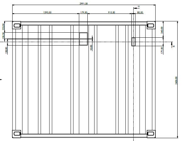
3.2. Container dimensions
| Description | Values |
|---|---|
Length, approx. |
2991 mm |
Width, approx. |
2438 mm |
Height, approx. |
3000 mm |
Surface area |
6.66 m2 |
Volume |
21.12 m3 |
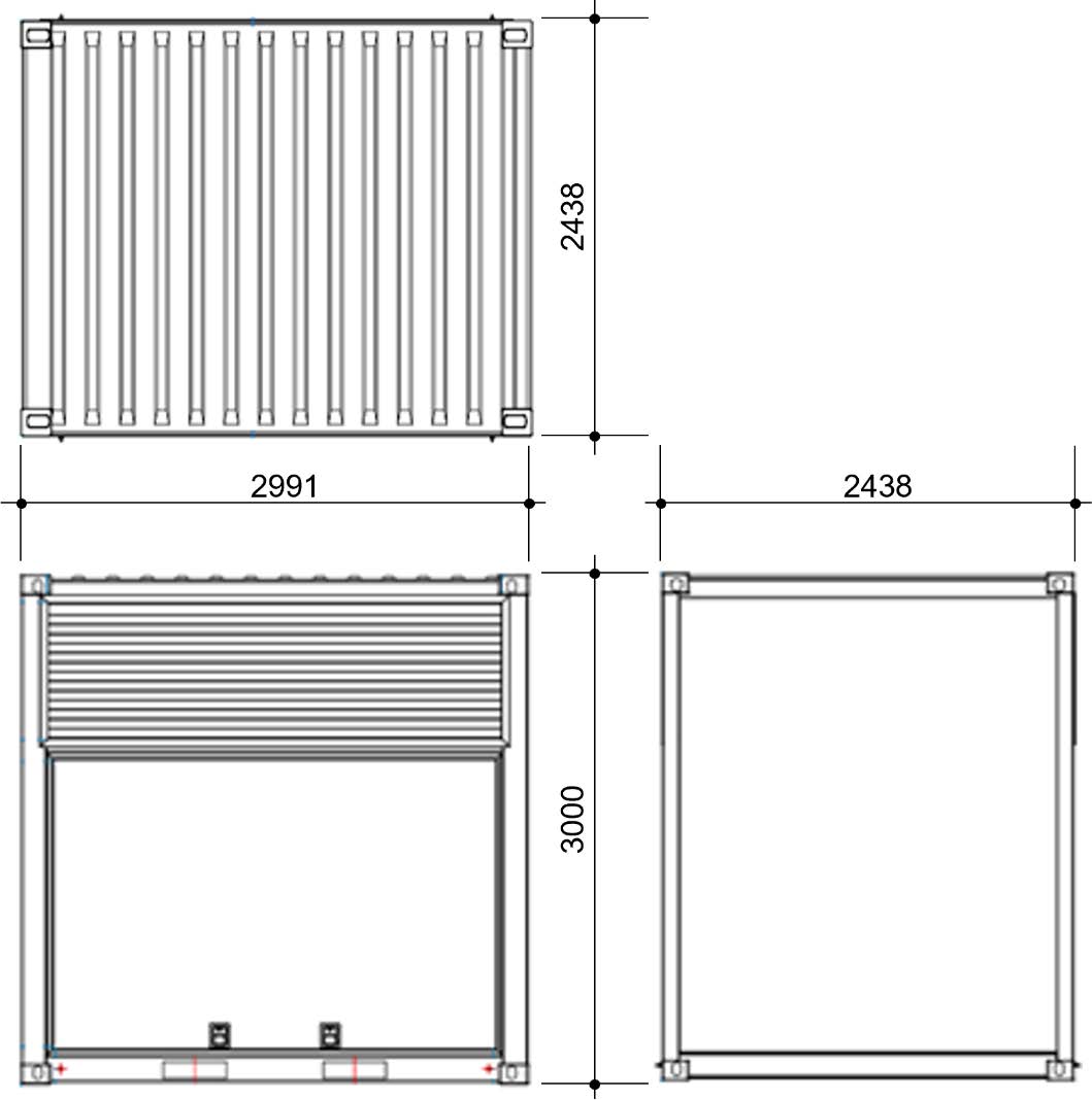
(A) Top view
(B) Front/rear side
(C) Sides (right/left)
3.3. Power and weight according to system configuration
As shown in the following table, the total weight varies according to the system configuration.
The cooling system is not included in the weight specifications and, if installed, adds 300 kg to the overall weight.
3.4. Battery information
3.4.1. BMW
The BMW battery is a lithium-ion polymer battery.
| Naming | Quantity/Size |
|---|---|
Length, approx. |
1660 mm |
Width, approx. |
964 mm |
Height, approx. |
174 mm |
Weight, approx. |
288 kg |
Usable battery capacity, approx. |
82 to 656 kWh |
C rate, max. |
1.07 |
Capacity per battery module, min. |
41 kWh |
Storage material |
Li-NMC/G-NMC/Carbon/Ceramic separator |
Nominal energy capacity |
42 kWh |
Usable energy capacity |
34.6 kWh |
Charging power in mains operation, max. |
50 kW |
Continuous power |
40 kW |
The usable battery capacity values vary depending on the system configuration. The smallest configuration comprises of 2 batteries and 1 inverter.
Technical data of the battery can be found in the manufacturer’s data sheet (Appendix, Applicable documents).
3.5. Inverter
3.6. Control cabinet
| Naming | Quantity/Size |
|---|---|
Power consumption |
22 kW |
Power fuse |
32 A |
Voltage |
400 V |
Mains frequency |
50 Hz |
3.7. Air conditioning unit
| Description | Quantity/Size |
|---|---|
Length, approx. |
1150 mm |
Width, approx. |
1200 mm |
Height, approx. |
640 mm |
Weight, approx. |
270 kg |
Coolant |
R134a |
Control accuracy |
± 3 K |
3.8. Fire alarm system
| Description | Quantity/Size |
|---|---|
Length, approx. |
333 mm |
Width, approx. |
195 mm |
Height, approx. |
140 mm |
Weight, approx. |
30 kg |
3.9. Components
Technical data of the system components can be found in the manufacturer’s documentation (Appendix, Applicable documents).
3.10. Ambient conditions
| Description | Quantity/Size |
|---|---|
Ambient temperature (container outside), min. |
-20 °C |
Ambient temperature (container outside), max. |
+50 °C |
Ambient temperature (container outside), max. |
+35 °C |
Relative humidity (operation) |
5 % to 95 % |
Relative humidity (storage) |
5 % to 95 % |
Operating altitude above sea level (NHN), max. |
2000 m |
Storage altitude above sea level (NHN), max. |
2000 m |
|
The C3 paint finish of the container is not suitable for marine environments. |
4. General description
4.1. Overview — Overall system
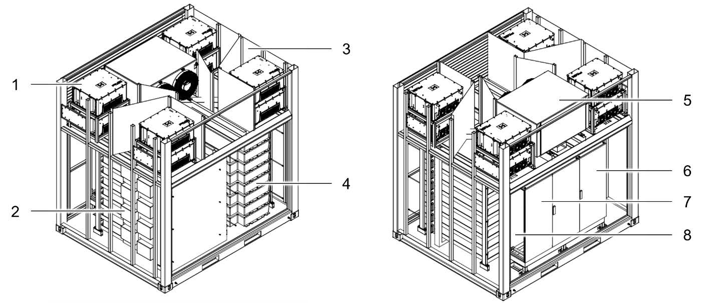
1 Inverter |
5 Cooling system (air conditioning unit) |
2 HV800 box |
6 Control cabinet (control system, FEMS and grid and plant protection) |
3 Container |
7 Low-voltage main distribution board incl. circuit breaker |
4 Battery stack (max. 16 batteries) |
8 Smoke aspiration system |
4.2. Components
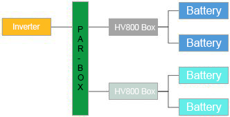
4.2.1. Energy storage system
The ESS consists of an inverter, an HV800 box and two batteries connected in series.
Optionally, additional battery packs can be connected in parallel to an inverter. To do this, a PAR box must be mounted in front of the HV800 boxes.
4.2.2. HV battery BEV SE09
The BEV SE09 HV battery is a lithium-ion battery. Two battery stacks with a maximum of 8 batteries each are installed in the system.
Further information on the batteries can be found in the manufacturer’s documentation (Appendix, Applicable documents).
4.2.3. Inverter
A maximum of 8 inverters (REFUstore 88k) or up to 6 inverters (KACO bp gridsave 92.0 kVA) can be used in the system to transfer power between the battery and the grid or vice versa.
Commissioning and monitoring of the inverters is carried out via the FEMS.
Further information on the inverters can be found in the manufacturer’s documentation (Appendix, Applicable documents).
4.2.4. HV800-Box
The HV800 box serves as an interface between the inverter and the batteries. Additional battery packs can be connected in series.
The protective circuit for the batteries is installed in the HV800 box.
4.2.5. FEMS
Information on FENECON Energy Management System can be found in the section Communication and Controlling, on docs.fenecon.de and in the manufacturer’s documentation (Appendix, Applicable documents).
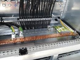
4.2.6. Low-voltage main distribution board
The low-voltage main distribution board is the power transfer point to the operating system. The power distribution of the inverters is controlled from here.
The connection to the Siemens circuit breaker is made in the low-voltage main distribution board. Depending on the design of the container, a Siemens circuit breaker for a maximum current of 800 A is installed for up to four inverters and for a maximum current of 1250 A for more than four inverters.
Optionally, the low-voltage main distribution board can also supply the control cabinet with power. Further information can be found in the External interfaces section.
4.2.7. Control cabinet
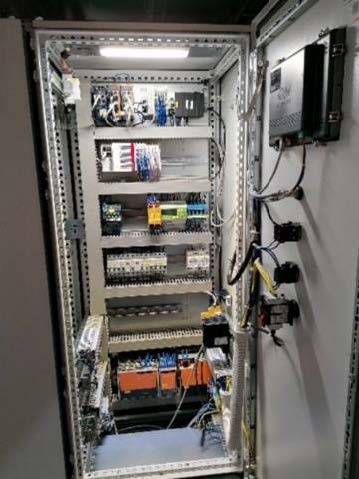
The control cabinet serves as the central control unit for the entire container. The communication connection and the interface for connecting the operator are located in the control cabinet.
The following components are located on the door of the control cabinet:
-
Display
-
Service-Port
-
Emergency-off push-button
-
Main switch
Find further information in the External interfaces section.
4.2.8. Integrated climate control unit RFCS-SON-016000-C-L-R25-3-IW
The air conditioning unit is an air-cooled compressor cooling system and is specially designed for the installation. The cooling capacity is 16 kW.
Further information on the integrated air conditioning unit can be found in the manufacturer’s data sheets (Appendix, Applicable documents).
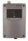
4.2.9. Option — Aspirating smoke detector Securiton ASD 531
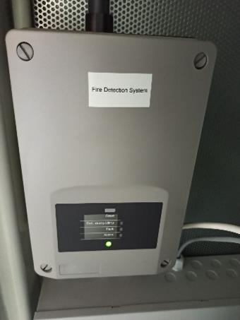
The fan generates a negative pressure in the intake pipe networks, which results in new air constantly entering the detector box via the intake pipes. The smoke sensor is therefore constantly supplied with new air samples from the areas to be monitored. If the smoke concentration exceeds the permissible value, the ASD 531 triggers an alarm.
Further information on the aspirating smoke detector can be found in the manufacturer’s documentation [applicable documents]).
4.2.10. Further equipment of the container
Maintenance doors
The maintenance doors are installed on the battery container and are closed using gas pressure springs.
The maintenance doors must be locked with U-locks to secure them. The key must be removed and kept in a safe place.
Ventilation openings in the inverter area
The ventilation openings in the inverter area are bolted to the container.
Option — Extinguishing water supply
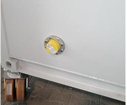
The container can be supplied with an optional extinguishing water feed opening on the side.
4.2.11. External interfaces
The system is equipped with the following external interfaces:
AC power connections
| Function | Design | Comment |
|---|---|---|
Main supply |
|
|
Control voltage |
Characteristics of the overcurrent protection device C32A |
|
Communication connections
| Function | Type | Amount per container | Comment |
|---|---|---|---|
Internet |
Network cable CAT6 or CAT7 with RJ45 plug |
1 |
If an LTE router is available, the network cable is not required. |
Internal network |
Network cable CAT6 or CAT7 with RJ45 plug |
1 |
|
Modbus RTU |
Li2YCY(TP) 2 x 2 x 0.22 |
1 |
|
Fire alarm system |
Two potential-free relay contacts |
1 |
Further information on the aspirating smoke detector can be found in the manufacturer’s documentation (Appendix, Applicable documents). |
Service port control cabinet |
Assign static IP address |
1 |
The static IP address can be used to access the internal network of the control cabinet. |
Emergency-off push-button |
Double-channel design |
1 |
Option — Additional emergency-off push-buttons can be integrated. |
4.3. Communication and Controlling
The battery storage system can be charged and discharged with control commands from the energy management system.
In normal operation, only read access to the measurement data is possible. The FEMS App "Modbus/TCP write access" can be purchased optionally for overriding the system.
4.3.1. FEMS
The FEMS connection box (HV800 box) is supplied fully wired and installed ready for connection.
The FEMS Online Monitoring enables access to the live data and historical data of the system at any time.
4.3.2. FEMS Apps
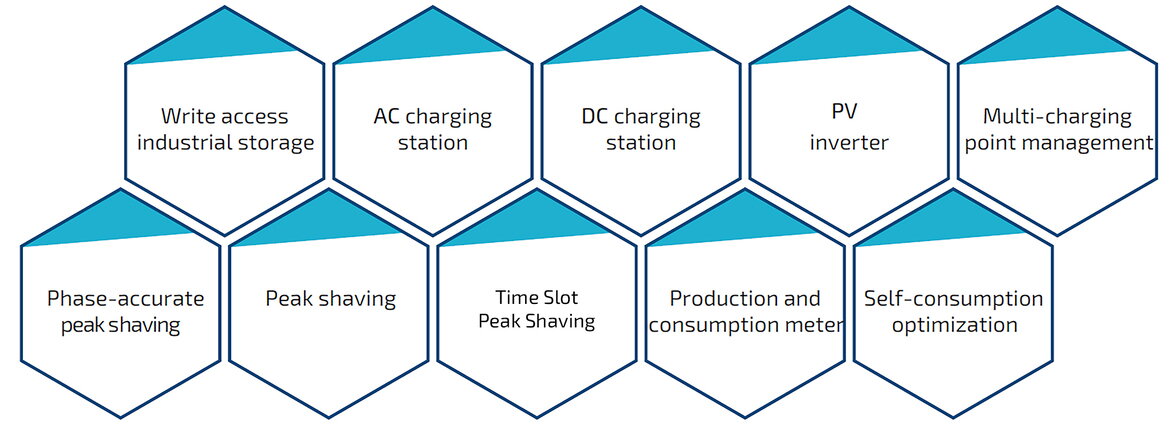
If required, energy management can also be expanded with additional FEMS apps. The FEMS app includes the software algorithm and a widget for FEMS Online Monitoring. With the help of the energy management system, it is possible to use the battery more effectively and thus increase PV self-consumption, for example.
FEMS Apps are available for all requirements. Each electrical energy storage system gets the FEMS apps it needs. New FEMS Apps can be added at any time as required. New FEMS Apps automatically interact with the existing ecosystem.
Further information is available at docs.fenecon.de.
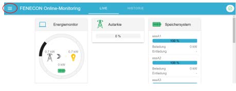
4.3.3. FEMS Online Monitoring
Access to FEMS Online Monitoring is available on the FENECON homepage in the top right corner.

In FEMS Online Monitoring, a distinction is made between the following two views:
-
Live view
-
Historical view
Live view
All current values are displayed in the live view.
Historical view
In the historical view, all values are displayed over a definable period in the past.
Visualization of the values
The values are visualized using widgets. A distinction is made between "flat widgets" and "advanced widgets". Flat widgets only show the relevant/simplified values. Clicking on the flat widget takes you to the advanced widget. This shows more detailed information (e.g. the power consumption curve for a day).
In the following example, a distinction is made between the energy monitor on the left, which shows basic information about the battery (e.g. grid withdrawal or grid feed-in) and the other widgets on the right, which can display more precise values (e.g. the self-sufficiency level or self-consumption).
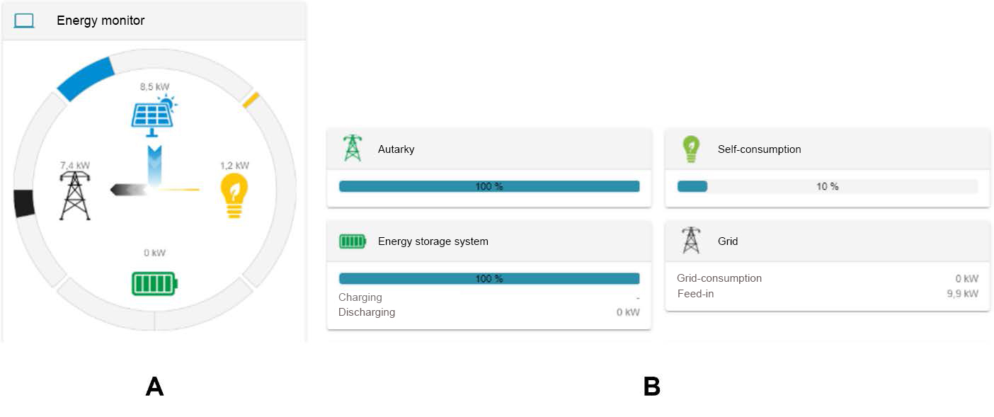
A: Energy monitor
B: Other widgets
Further information on {oem-full-name} can be found at docs.fenecon.de and in the technical documentation (Appendix, Applicable documents).
4.3.4. Communication protocol
The system can receive charge/discharge commands via a Modbus TCP interface. It is necessary to communicate with each battery pack PCS system individually.
|
The REFU-PCS supports the SunSpeck MESA communication protocol and the values represented by this standard protocol. |
Access to the communication protocol
→ Have the FEMS number at hand.
-
Open the website portal.fenecon.de
-
Log in to the system in the menu displayed and then enter the FEMS number of the system you are looking for in the search field.
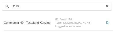
-
Then click on the FEMS you are looking for to access the various widgets.
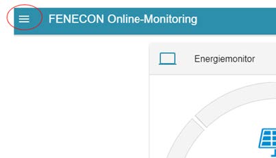
-
Click on the burger menu in the top left of the taskbar.
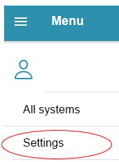
-
Select the >>Settings<< entry.
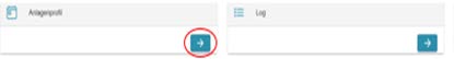
-
Select the blue arrow under the >>Plant profile<< tab.
-
Then scroll down until you find the file with the name >>ctrlApiModbusTcp0<<.

-
Click on the black arrow.
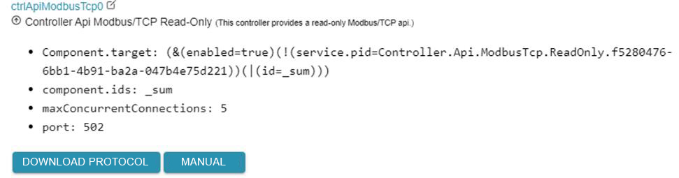
-
Click >>DOWNLOAD PROTOCOL<< to download the communication protocol.
The FEMS App provides a Modbus/TCP slave API interface. The Modbus interface is configured as follows:
| Parameters of the FEMS app Modbus/TCP-API, read-only | |
|---|---|
Port |
502 |
Unit ID |
1 |
Function codes |
03 (Read Holding Registers) |
04 (Read Input Registers) |
|
The Modbus interface enables access to the channels of the "_sum" component as standard.
The individual Modbus protocol for the respective operator system can be downloaded as an Excel file via FEMS Online Monitoring. The following quick overview contains the most important data points:
Address (address) |
Name |
Type |
Value/Description |
Unit |
Access |
200 |
Component-ID |
string16 |
_sum |
RO |
|
222 |
State |
enum16 |
0:Ok, 1:Info, 2:Warning, 3:Fault |
RO |
|
302 |
EssSoc |
uint16 |
State of charge |
Percent [%] |
RO |
303 |
EssActivePower |
float32 |
AC-side active power of the electrical energy storage including excess DC generation with hybrid inverter |
Watt [W] |
RO |
309 |
EssReactivePower |
float32 |
AC-side reactive power of the electrical energy storage |
Volt Ampere Reactive [var] |
RO |
315 |
GridActivePower |
float32 |
Active power at grid connection point |
Watt [W] |
RO |
317 |
GridMinActivePower |
float32 |
Minimum active power measured per grid connection point |
Watt [W] |
RO |
319 |
GridMaxActivePower |
float32 |
Maximum active power per measured active power at the grid connection point |
Watt [W] |
RO |
327 |
ProductionActivePower |
float32 |
Active power of the PV yield and, if applicable, yield from external inverters |
Watt [W] |
RO |
329 |
ProductionMaxActivePower |
float32 |
Maximum measured active power of the PV system |
Watt [W] |
RO |
331 |
ProductionAcActivePower |
float32 |
Active power of the external AC inverters |
Watt [W] |
RO |
339 |
ProductionDcActualPower |
float32 |
Power of the DC generation of the hybrid inverter |
Watt [W] |
RO |
343 |
ConsumptionActivePower |
float32 |
Active power of the electrical consumption |
Watt [W] |
RO |
345 |
ConsumptionMaxActivePower |
float32 |
Maximum active power of electrical consumption ever measured |
Watt [W] |
RO |
351 |
EssActiveChargeEnergy |
float64 |
Cumulative electrical energy of the AC-side battery charging incl. excess PV generation at the hybrid inverter |
Watt hours [Wh] |
RO |
355 |
EssActiveDischargeEnergy |
float64 |
Cumulative electrical energy from electrical energy storage to consumption via AC output of the inverter incl. PV generation |
Watt hours [Wh] |
RO |
359 |
GridBuyActiveEnergy |
float64 |
Cumulative electrical energy from grid consumption |
Watt hours [Wh] |
RO |
363 |
GridSellActiveEnergy |
float64 |
Cumulative electrical energy of the grid feed-in |
Watt hours [Wh] |
RO |
367 |
ProductionActiveEnergy |
float64 |
Cumulative electrical energy of PV generation + external inverter generation |
Watt hours [Wh] |
RO |
371 |
ProductionAcActiveEnergy |
float64 |
Cumulative electrical energy of the external inverters |
Watt hours [Wh] |
RO |
375 |
ProductionDcActiveEnergy |
float64 |
Cumulative electrical energy of the PV generation of the inverter |
Watt hours [Wh] |
RO |
379 |
ConsumptionActiveEnergy |
float64 |
Cumulative electrical consumption |
Watt hours [Wh] |
RO |
383 |
EssDcChargeEnergy |
float64 |
Cumulative DC electrical energy of battery charging |
Watt hours [Wh] |
RO |
387 |
EssDcDischargeEnergy |
float64 |
Cumulative DC electrical energy of storage discharge |
Watt hours [Wh] |
RO |
415 |
EssDischargePower |
float32 |
Actual AC-side active power of the electrical energy storage |
Watt [W] |
RO |
417 |
GridMode |
enum16 |
1:On-Grid, 2:Off-Grid |
RO |
Data types
The following data types are used in the Modbus protocol:
-
uint16 — Unsigned integer in a Modbus 16-bit word
-
uint32 — Unsigned integer in a Modbus 32-bit double word
-
float32 — Floating point number in IEEE 754 format in a Modbus 32-bit double word
-
float64 — Floating point number in IEEE 754 format in four Modbus words (64-bit)
-
string16 — String in ASCII format with two characters per Modbus 16-bit word
|
For data points that are longer than a 16-bit word, the correct length must be read in each case. Otherwise a read error is generated. |
Undefined data
Depending on the system, individual data points may be permanently unavailable (e.g. because there is no generator or electrical energy storage) or temporarily unavailable (e.g. in the event of a communication error with the grid meter). In this case, the following values must be read out via the API:
| Data type | Undefined value |
|---|---|
uint16 |
0xffffff |
uint32 |
0xffffffffff |
float32 |
0x7fc000 |
float64 |
0x7ff8000000 |
string16 |
0x00000000000000000000000000000000 |
Further information can be found at https://docs.fenecon.de/en/fems/fems-app/App_ModbusTCP_Lesezugriff.html.
Extension — FENECON Home 10 App Modbus/TCP-API write access
As with the read-only interface, access to the channels of the "_sum" component must be enabled as standard. Access to other components is enabled on a project-specific basis (e. g. enabling controllable electricity storage systems or charging stations via the interface).
The Modbus table can be downloaded in the same way as for the read-only interface. The Modbus table is structured in blocks. Each block corresponds to a component and differs depending on which properties the component supports.
Each block has a header data area, which is structured as follows:
| Address offset | Description | Data type |
|---|---|---|
0 |
Component ID |
string16 |
16 |
Length of the entire block |
uint16 |
17-19 |
Reserved |
|
20 |
Hash of the nature name |
uint16 |
21 |
Length of the Nature block |
uint16 |
All component blocks and nature blocks together result in the individual Modbus table for an FEMS.
There are the following three access variants:
-
RO (Read-Only)
-
RW (Read-Write)
-
WO (Write-Only)
Find further information at https://docs.fenecon.de/en/fems/fems-app/App_ModbusTCP_Schreibzugriff.html.
4.3.5. Lightning and surge protection
The system is equipped with overvoltage and lightning protection.
External lightning protection
The outer steel container wall is 4 mm thick, so that no interception rods are required and targeted discharge takes place via the frame construction and/or crossbars.
Earthing system
The earthing system is based on DIN EN 62305 (in accordance with DIN 18014). If necessary, local requirements must be taken into account.
-
NIRO V4A materials
-
Recommended resistance value according to DIN EN 62305: ~10 Ohm
-
Designed as ring equipotential bonding or, alternatively, with earthing rods
Internal lightning protection
The internal lightning protection (based on the standard: DIN EN 62305, local requirements may have to be taken into account) comprises the following three main parts of the container:
-
Mains voltage contactor
-
Contactor of the communication unit
-
Contactor for the supply line for the integrated air conditioning units and the smoke extraction system (outdoor units)
Overvoltage protection
Overvoltage protection is provided on the auxiliary voltage, the supply line, the RS485 interface and the LAN port by various uninterruptible power supplies (UPS).
4.4. Signal transmitter
4.5. Exhaust air and supply air of the inverters in the container
4.5.1. REFU container
The REFU inverters are installed horizontally in the container. As the inverters draw in and blow out air opposite each other, the result for the container as a whole is that air is drawn in at the protective gratings on the control cabinet side and the warm exhaust air is blown out at the gratings on the battery side.
5. Assembly
The container is delivered ready for connection and still needs to be set up and connected on site.
5.1. Notes on installation
-
The container must be positioned at the installation site on a suitably dimensioned foundation with sufficient load-bearing capacity.
-
If necessary, the foundation must be designed to prevent slippage and movement.
-
The installation site must be well lit.
-
The area should be contactor protected.
-
If contact with vehicles (e.g. in a parking lot or on a road) is conceivable/possible, the system must be protected.
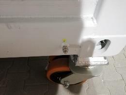
Earthing system
The earthing lugs can be connected directly to the container with screw connectors at the marked points of the earthing connections on the container.
The earthing system must be designed in accordance with the locally applicable requirements.
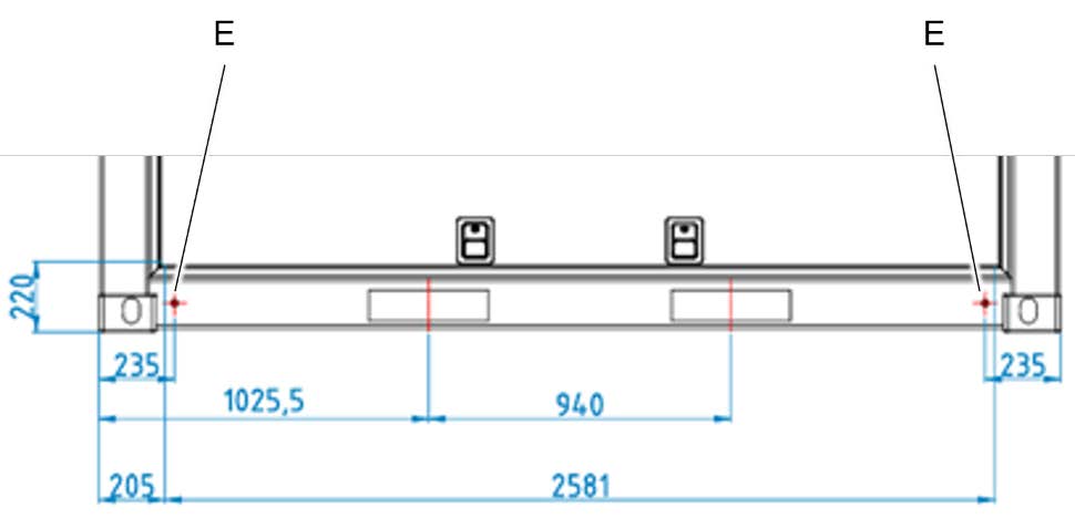
E — Earthing connection points on the container
Cable entry
The container has a total of three cable entry openings in the area of the low-voltage main distribution board and the control cabinet. The cables must be fed into the container from below. The necessary normative bending radius must be observed when inserting the cable.
1 — Cable entry NSHV 2 x (view from below)
2 — Cable entry for control cabinet (view from below)
The openings are sealed with a customized cable gland from Roxtec.
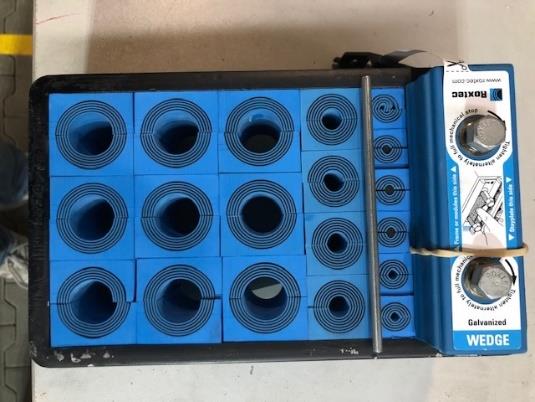
Further information on the assembly of Roxtec cable glands can be found in the manufacturer’s data sheets (Appendix, Applicable documents).
5.1.1. Space requirement at the installation site
The container is designed so that access to the battery storage system must be possible from the front and rear during installation and for maintenance purposes. It is also recommended to maintain a distance of 1 m from existing buildings on the left and right side walls.
The following distances must be observed:
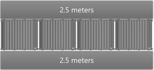
Arrangement of several containers
If several containers are arranged at one system location, they can be positioned in a row. It is recommended to plan a distance of 3 m after every 4 containers in a row for maneuvering purposes.
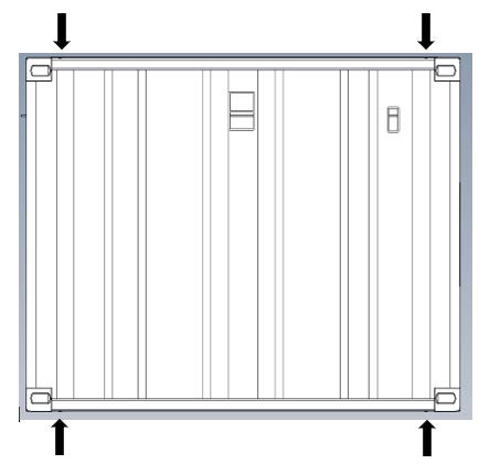
5.1.2. Foundation
The container must be positioned on a sufficiently dimensioned foundation at the installation site. The foundation can be constructed as a point foundation consisting of 4 points over two strip foundations or on a single foundation. The cable entries must remain freely accessible. Information on the dimensions of the foundation can be determined using the load transfer points of the containers.
Further information on weight transfer and load transfer points can be found in the structural analysis reports for the containers and the weight table (Appendix, Applicable documents).
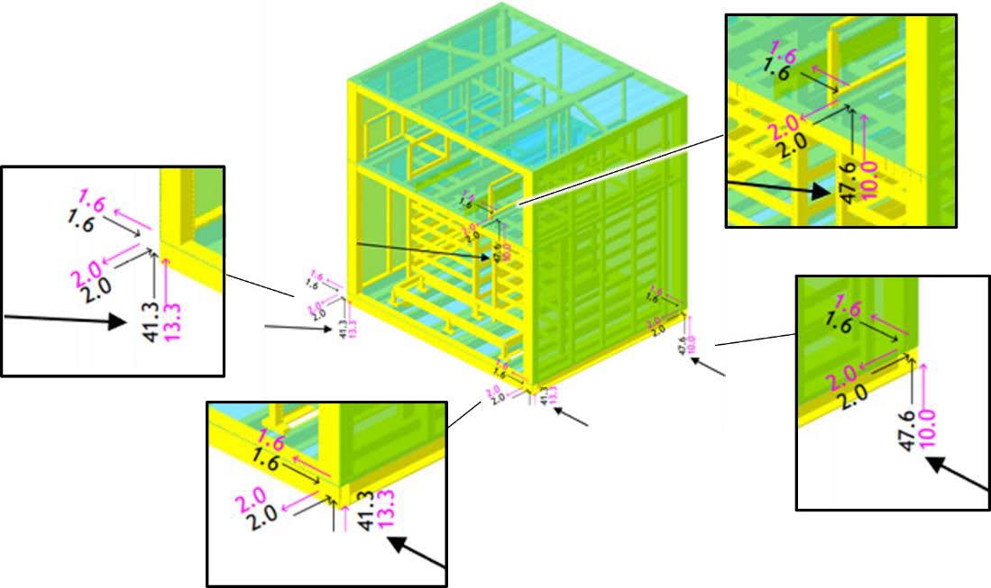
Load transfer points — REFU container
The load transfer points are shown in kN in the following diagram.
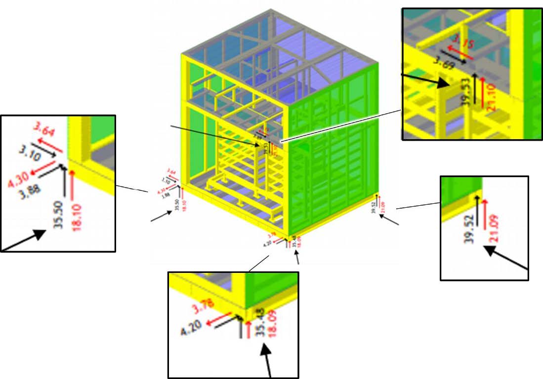
Load transfer points — KACO containers
The load transfer points are shown in kN in the following diagram.
5.1.3. Electrical connection
Safety instructions
|
Electrical voltage
|
|
Incorrect earthing Death or serious injury to the body or limbs due to electric shock caused by incorrect earthing.
|
-
A residual current device (RCD) with a rated residual current of 5 A must be connected upstream of the main supply of the electrical energy storage system (see 4.2.11: External interfaces). For the product variant with PRAMAC inverters, this must be all-current sensitive (type B). Type A is sufficient for the product variant with KACO inverters (see appendix, Applicable documents)
-
Only the specified batteries must be used (Appendix, Applicable documents).
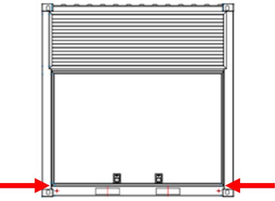
Connection — Earthing systems
The container has 2 prepared earthing points under each of the maintenance doors.
We recommend earthing with a cable lug (size M8) at all earthing points of the container, as well as earthing the housing and the copper rail of the low-voltage main distribution board.
In Germany, the measurement on the foundation earth electrode must result in a value of <1 Ohm.
When planning the electrical connection for the battery storage system, the electrical connection must be planned at an early stage. The following overview list shows the necessary cables.
Main supply
| Function | Execution | Note | Measures |
|---|---|---|---|
Main supply |
|
|
|
| Function | Execution | Amount per container | Note | Measures |
|---|---|---|---|---|
|
||||
Control voltage |
Characteristic of the overcurrent protective device C16A |
1 |
Only required if control voltage is supplied externally and not internally via the main supply |
Optional:
|
Communication connections
| Function | Execution | Amount per container | Note | Measures |
|---|---|---|---|---|
Internet |
Network cable, CAT6 or CAT7 with RJ45 plug |
1 |
Only required once on the master container |
Lay an RJ45 cable from the operator network to the container and connect to terminal F8 according to the circuit diagram. |
Master/slave |
CAT6 or CAT7 network cable with RJ45 plug |
2 |
Only required if several containers are installed at one location. |
|
External measurement/meter |
Li2YCY(TP) 2 x 2 x 0.22 or similar |
1 |
|
|
Cable entries
Further information on the exact position and dimensions of the cable entries can be found in the installation instructions (section Cable entries).
Further information on selecting the appropriate cable cross-section for copper cables can be found in the appendix (Appendix, Applicable documents).
5.1.4. Single-line diagram
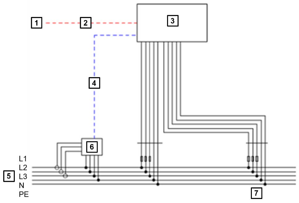
1 |
Operator’s internet connection |
2 |
RJ45 |
3 |
Industrial ESS |
4 |
RS485 or RJ45 |
5 |
Grid |
6 |
Meter |
7 |
Supply voltage |
|
The cables described here are not included in the scope of delivery. |
An external power supply/auxiliary power supply can be supplied as an option.
The exact connections on the container are contained in the circuit diagram (Appendix, Applicable documents).
6. Commissioning
6.1. Initial commissioning
Initial commissioning is not considered in the installation and service instructions, as this phase has already been carried out by the manufacturer during the factory acceptance test.
6.2. Requirements for commissioning
6.2.1. Internet connection
First, a permanent internet connection must be established to ensure access to FENECON Online Monitoring. This can basically be ensured by two different options. By using a LAN cable or by using a VPN router.
LAN cable option
-
The connection via LAN cable is described in Table 24 (section Electrical connection).
VPN router option
-
A SIM card with approx. 15 GB data volume is required to provide the internet connection.
-
Send the SIM card to FENECON.
-
The necessary configurations and the installation of the router with SIM card in the storage container are then carried out there.
-
Further information can be found in the manufacturer’s installation and service instructions (Appendix, Applicable documents).
6.2.2. Network configuration
In the standard configuration, the FEMS obtains the network configuration via a DHCP server. The configuration of a static IP can only be implemented via remote maintenance. Keep the following information contacting the FENECON Service at hand:
-
Desired IP address
-
Net mask
-
Gateway
-
DNS server
The network configuration can be implemented in three different ways.
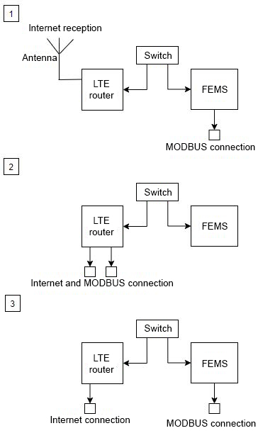
-
The internet is provided with an antenna, the Modbus connection is made at FEMS.
-
The internet and the Modbus connection are connected to the LTE router.
-
The internet connection is connected to the router, the Modbus connection is made at FEMS.
6.2.3. Firewall
The following services run on the FEMS and require an active internet connection:
-
DNS
-
FENECON package updates
-
Operating system package updates
-
Operating system security updates
-
FEMS Online Monitoring
-
Time synchronization
-
Remote maintenance
6.2.4. System-Update
As part of the system update, the latest software is downloaded from www.fenecon.de and installed. The system update takes place once a day at around 5 a.m.
6.3. Commissioning procedure
Only commence commissioning after all standardized measurements required by national regulations have been carried out at the place of use before initial commissioning.
Deactivate emergency-off
-
First check if the emergency-off push-button on the control cabinet is deactivated (i.e. not actuated).
Switch on grid and plant protection/main switch
-
Check whether the network monitoring relay still needs to be adapted to specific country standards. Information on the setting can be found in the instructions of the device manufacturer Tele-Haase NA03.
-
Switch the main AC switch on the control cabinet to ON position.
-
The battery storage control unit starts up.
-
The integrated mains monitoring relay checks whether the mains parameters are within specified limits. If this is the case, the main circuit breaker is switched on after a standardized waiting time
-
Once the supply voltage has been applied to the system, the system can be started locally on the display in the menu.
-
-
Overvoltage protection
-
Check that all UPS are installed and ready for operation.
-
Switch on the UPS.
System start
-
Tap on the display and log in with the password
admin. -
Then tap on the three stripes at the top left to show the menu bar.
-
Then select "FEMS setting".
|
Alternatively, the system can also be started automatically via the Modbus interface. The communication protocol can be downloaded from the system’s Online Monitoring. For this process, follow the documentation of the FEMS controller. |
FEMS Apps
-
Proceed with the commissioning of the applications according to the extra commands if the system is to be controlled by means of integrated applications.
Lock maintenance doors
|
To be able to press the maintenance door, the help of a second person may be required for the next step. |
-
Close both maintenance doors.
-
Check that the two maintenance doors on both sides are properly closed and latched.
-
Lock both maintenance doors with the key.
-
Then send the commissioning report to FENECON GmbH.
6.4. Post-commissioning measures
-
During operation, the system can be monitored via the display on the control cabinet. When the screen is tapped, the current system parameters of the battery storage can then be viewed. A detailed description of the monitoring function can be found in the documentation for the FEMS control unit (Appendix, Applicable documents).
-
Alternatively, complete monitoring of the system is also possible via the integrated remote access or the Modbus interface. Further information on this can be found in the documentation for the FEMS controller (Appendix, Applicable documents).
-
Carry out and record visual inspections of the system (leaks, possible condensate, damaged pipes, damaged insulation, damaged seals, etc.).
-
Optional — Additional on-site check of the functionality of the fire monitoring and emergency-off function. However, these were already tested during the initial commissioning, the factory acceptance test.
6.5. Commissioning after relocation
Information on recommissioning after relocation can be found in the Commissioning procedure section.
6.6. Recommissioning after a longer down time
Information on recommissioning after a longer down time can be found in the sections Commissioning procedure and [Starting/stopping system operation]).
6.7. Recommissioning after a fault
Information on recommissioning after a longer down time can be found in the sections Commissioning procedure and [Switching on after fault "Power failure"]).
6.8. Operation
There are no persons in the system during operation.
The system is locked and inaccessible.
6.9. Safety instructions
|
EMC radiation inside the enclosure
|
|
Gas leakage Death or serious injury to body and limbs due to explosion of an explosive gas caused by damage to the container or its components.
|
-
If noise or vibrations occur during operation, locate and rectify the issue.
-
Operating the system without earthing is prohibited.
-
Entering the container during operation is prohibited.
-
The maintenance doors must be closed while the system is in operation.
-
The keys for access to the system (e. g. maintenance doors) must only be issued to authorized specialist personnel. It is recommended that the issuing of keys is recorded.
-
In the event of defects in the system, inform FENECON GmbH (section Maintenance, section FENECON Service).
-
In the event of electrolyte leakage, wear suitable protective equipment as specified by the battery manufacturer (safety data sheet) (Appendix, [applicable documents]).
6.10. Operating and control points
The following operating and control points are located on the control cabinet:
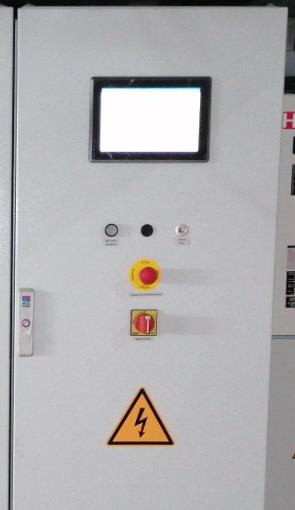
| List item | Description | Position | Function |
|---|---|---|---|
1 |
Display |
The system is accessed via the display on the control cabinet. |
|
2 |
Acknowledgement push-button |
The acknowledgement key must be pressed after unlocking the emergency-off to confirm this. |
|
3 |
Emergency-off push-button |
pressed |
Emergency-off tripped |
unlocked |
normal operation possible |
||
4 |
Main switch with emergency-off function |
I |
System AC-side connected |
O |
System disconnected on AC side |
6.11. Adjustment work
The installation and service instructions do not consider the adjustment work on the system, as the basic settings are implemented by the manufacturer itself and are completed at the time of placing on the market and/or commissioning.
The operator can variably select an automatic start/stop function and the start of Peak Shaving. Find information about this at docs.fenecon.com.
6.12. Operation requirements
-
All assembly and commissioning steps described above have been carried out properly or are being complied with.
-
Access is only possible for authorized persons.
-
All protective measures (e. g. acrylic glass to protect against electric shocks) have been installed.
-
There are no errors/faults.
6.13. Start/stop system operation
6.13.1. Start system operation
Configure the network interface on the laptop
-
Assign the configuration of the network interface on the laptop:
→ IP address:10.4.0.101.
→ Subnet mask:255.255.0.0to configure the network interface on the laptop.
-
Connect the service LAN port on the control cabinet to the laptop.
-
Connect to the BCS via the browser on your laptop:
→ Call up IP address10.4.0.31
-
Enter user name and password in BCS:
→ User name:customer
→ Password:operator -
Log in to FEMS Online Monitoring:
→ With the existing access data. -
Switch on the main switch.
-
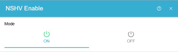
Select the "NSHV Enable" widget/digital output in Online Monitoring.
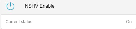
-
Set "NSHV Enable" to "On".
-
Check the circuit-breaker indicator on site to see whether it is showing "On" (indicator is red).
-
Unlock the emergency-off push-button on the control cabinet.
-
Press the white push-button on the control cabinet door to acknowledge the emergency-off.
→ The white illuminated push-button lights up.
|
If additional emergency-off push-buttons have been installed, these must also be confirmed. |
-
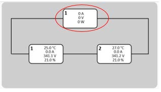
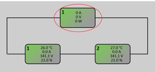
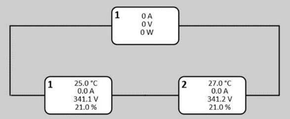
In the BCS, click on the box marked in the image to open information on the selected PCS.
→ The display must be completely white.
|
|
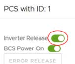
-
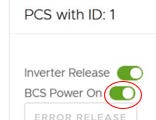
First press the lower "BCS Power ON" button marked in the image above for all electrical energy storage units individually. Start with the first PCS and press the "BCS Power ON" button down to the last PCS.
|
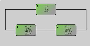
Before switching on the next PCS, wait until the previous PCS has finished switching on. The display changes color. |
|

|
-
Then press the upper "Inverter Release" button marked in the image above for all electrical energy storage units individually.
Set the battery status to "Default".
-
In FEMS Online Monitoring, click on the icon in the taskbar.
-
Click on the "Settings" menu in FEMS Online Monitoring.

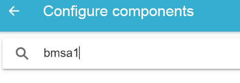
-
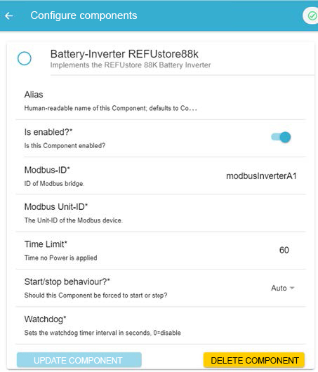
In FEMS Online Monitoring, click on the arrow button under "Configure components".
|
Set the battery status to "Default" for all battery management systems and then update the components. To do this, proceed as follows. |
-
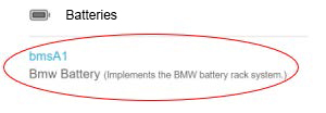
Enter "bmsa1" in the search field.
-
Select the "bmsA1" entry from the "Batteries" category.
-
In the line, change the "Battery state" setting to "Default" and then press the "UPDATE COMPONENTS" button.
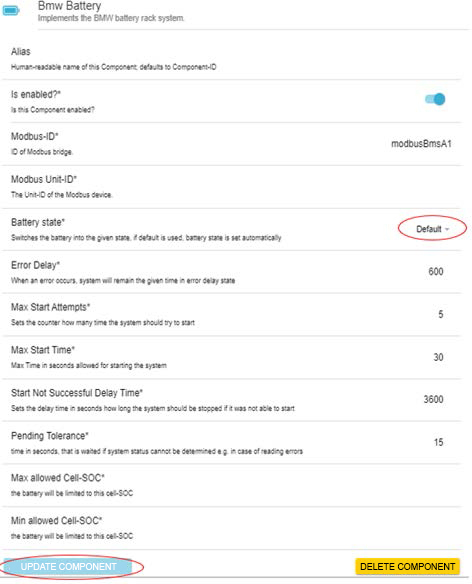
-
Carry out these steps (21 to 23) for the remaining BMS A1-A4/B1-B4 as well.
|
Containers that are not fully equipped may also have less BMS. |
-
Check the display in the BCS interface.
| Display | Meaning |
|---|---|
Green |
Everything is OK |
Red |
Contact FENECON GmbH |
Yellow |
Wait until the color changes |
Set ESS to "Start"
-
Click on the "Settings" menu in FENECON Online Monitoring.
-
In FENECON Online Monitoring, click on the arrow button under "Configure components".
-
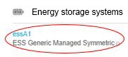
Enter "essa1" in the search field.

-
Select the "essa1" entry from the "Storage systems" category".
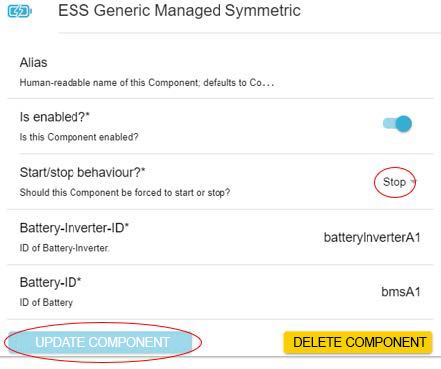
-
For each ESS A1-B4 individually, set "Start" in the "Start/stop behavior?" line and then update the component.
Check inverter
-
Click on the "Settings" menu in FENECON Online Monitoring.
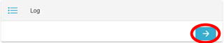
-
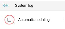
In FENECON Online Monitoring, click on the arrow button under "Log".

-
Switch off "Automatic update".
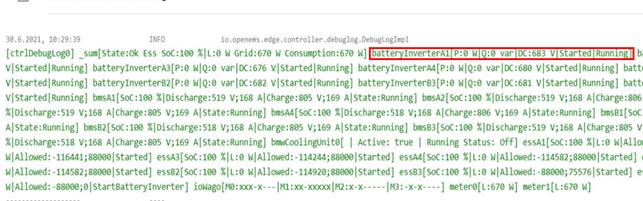
-
Check whether "Started/Running" or "GoRunning/StartingUp" is set for all inverters (marked red for inverter A1 in the image as an example).
-
If these entries are made for all inverters, the switch-on process is complete.
-
|
If these entries are not available for all inverters, contact Fenecon GmbH. |
Manual control charge/discharge" option
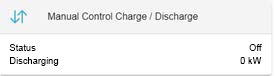
The power can be set under the menu item "Manual control charge/discharge".
-
Switch on the controller and enter manual power.
-
Then deactivate the controller so that the set applications work, as the controller overwrites the other data/settings during operation.
6.13.2. End system operation
Configure the network interface on the laptop
-
Assign the configuration of the network interface on the laptop:
→ IP address:10.4.0.101.
→ Subnet mask:255.255.0.0to configure the network interface on the laptop.
-
Connect the service LAN port on the control cabinet to the laptop.
-
Connect to the BCS via the browser on your laptop:
→ Call up IP address10.4.0.31
-
Enter user name and password in BCS:
→ User name:customer
→ Password:operator -
Log in to FEMS Online Monitoring:
→ With the existing access data.
Set ESS to "Stop"
-
In FEMS Online Monitoring, click on the icon in the taskbar.
-
Click on the "Settings" menu in FEMS Online Monitoring.
-
In FEMS, click on the arrow button under "Configure components".
-
Enter "essa1" in the search field.
-
Select the "essa1" entry from the "Storage systems" category.
-
Set each ESS A1-B4 individually to "Stop" in the "Start/Stop behavior" line and then update the component.
Check inverter
-
Click on the "Settings" menu in FEMS Online Monitoring.
-
In FEMS Online Monitoring, click on the arrow button under "Log".
-
Switch off "Automatic update".
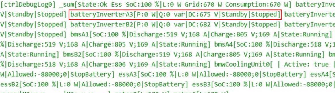
-
Check whether "Standby/Stopped" is set for all inverters (inverter A3 is marked red in the image as an example).
-
If these entries are made for all inverters, the switch-off process is complete.
-
|
If these entries are not available for all inverters, contact Fenecon GmbH. |
Set battery status to "Stop"
-
In FEMS Online Monitoring, click on the icon in the taskbar.
-
Click on the "Settings" menu in FEMS Online Monitoring.
-
In FEMS Online Monitoring, click on the arrow button under "Configure components".
|
For all battery management systems, set the battery status to "Stop" and then update the components. To do this, proceed as follows. |
-
Enter "bmsa1" in the search field.
-
Select the "bmsA1" entry from the "Batteries" category.
-
For all bmsA1-B4, change the "Battery state" line individually to "Stop" and then press the "UPDATE COMPONENT" button.
-
In the BCS, click on the box marked in the image to open information on the selected PCS.
-
The display should be green/gray.
-
-
First switch off the upper "Inverter Release" button marked in the image above for all electrical energy storage units individually. Start with the first PCS and switch off the "Inverter Release" button down to the last PCS.
-
Then switch off the lower "BCS Power On" button for all PCSs individually. Start with the first PCS and switch off the "Inverter Release" button down to the last PCS.
|
Before switching off the next PCS, wait until the previous PCS has finished switching off. The display changes color to white. |
-
Press the emergency-off push-button when all displays are white.
-
Switch off the main switch on the control cabinet.
-
Select the "NSHV Enable" widget/digital output in Online Monitoring.
-
Set "NSHV Enable" to "OFF".
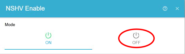
-
Check the circuit breaker indicator on site to see whether it is "Off" (indicator is green)
-
The switch-off process is complete.
-
|
If the circuit breaker indicator shows "On" (indicator is red), contact Fenecon GmbH. |
6.13.3. Switching on after "power failure" fault
Check digital inputs
-
Log in to FEMS Online Monitoring.
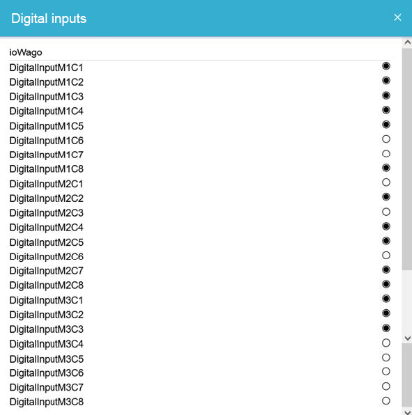
-
Switch on widget/digital inputs.
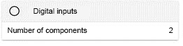
-
The following image should be displayed:
Check battery inverter in log
-
In FEMS Online Monitoring, click on the icon in the taskbar.
-
Click on the "Settings" menu in FEMS Online Monitoring.
-
In FEMS Online Monitoring, click on the arrow button under "Log".
-
Switch off "Automatic update".
-
Check the status of all battery inverters.
|
If "Started/Running" or "GoRunning/StartingUp" is displayed (inverter A1 marked red in the image as an example), the system has automatically switched back on. If not, proceed as follows. |
-
In FEMS Online Monitoring, click on the icon in the taskbar.
-
Click on the "Settings" menu in FEMS Online Monitoring.
-
In FEMS Online Monitoring, click on the arrow button under "Configure components".
-
Enter "batteryinverter" in the search field.
-
Set all battery inverters individually to "Stop" in the "Start/stop behavior?" line and then update the component.
Set all ESS to "Stop"
-
Enter "essa1" in the search field.
-
Select the "essA1" entry from the "Storage systems" category.
-
For each ESS A1-B4 individually, set the "Start/Stop behavior?" line to "Stop" and then update the component.
-
Then set all battery inverters in the "Start/Stop behavior" line to "Auto" and proceed as described above.
-
Then set all ESS for "Start/Stop behavior" to "Auto" and proceed as described above.
Check in log
-
Check whether "running" or "started running" is displayed for all battery inverters (inverter A1 is marked red in the image as an example).
-
If "running" or "started running" is displayed for all battery inverters, the connection procedure is complete.
-
|
If "running" or "started running" is not displayed for all battery inverters, contact FENECON GmbH. |
Manual control charge/discharge" option
The power can be set under the menu item "Manual control charge/discharge".
-
Switch on the controller and enter manual power.
-
Then deactivate the controller so that the set applications work, as the controller overwrites the other data/settings during operation.
6.14. Monitoring of system operation
The system is monitored via an industrial VPN router and the internet.
The system/system component data can be called up at any time from the remote maintenance center.
6.14.1. Monitoring
|
During operation, the system can be monitored via the display on the control cabinet or via portal.fenecon.de. |
-
Tap on the screen.
-
The current system parameters of the battery storage system are displayed.
-
|
A detailed description of the monitoring functions can be found in the FEMS controller documentation. Alternatively, complete monitoring of the system is also possible via the integrated remote access or the Modbus interface. Further information on this can be found in the FEMS controller documentation. |
Fault messages
|
Information on how to register can be found in the FEMS section or via portal.fenecon.de. |
-
Log in to FEMS Online Monitoring.
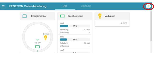
-
Check the system status by the color of the symbol at the top right.
| Display | Meaning |
|---|---|
Green check mark |
Everything is OK |
Orange exclamation mark |
Warning |
Red exclamation mark |
Error |
|
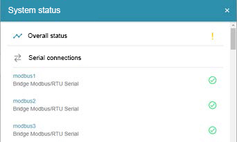
After clicking on the icon, a detailed overview of the existing warning or error is displayed. |
-
Click on the icon at the top right to display the system status.
-
Check the status of the components.
| Display | Meaning |
|---|---|
Green check mark |
Everything is OK |
Orange exclamation mark |
Warning |
Red exclamation mark |
Error |
-
Click on the blue arrow to the left of the exclamation mark to display further information on the error in the event of an error.

|
For some error messages, no text is yet stored in the error analysis. Later updates will add these entries. |
FEMS cannot be reached
If the FEMS cannot be reached via the FEMS Online Monitoring, the following error message is displayed:
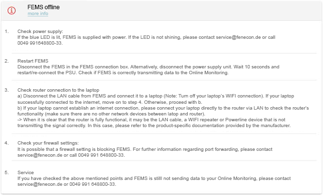
-
Carry out the steps specified in the error message.
Emergency-off
To disconnect the HV battery connections in critical cases and switch off the battery storage system internally, the emergency-off push-button must be pressed.
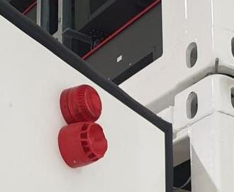
Fire monitoring (optional)
The container has an optional integrated fire monitoring system. This fire monitoring system detects a fire at a very early stage and shuts down the container immediately. A siren signals the alarm on site.
|
A possible false alarm must be deactivated directly on the unit of the fire monitoring system by pressing the [RESET] push-button. |
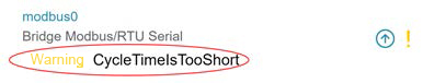
6.14.2. Messages in Online Monitoring
The meanings of various errors, warnings and information are listed below.
Error meaning
| Name | Description | Affected Unit |
|---|---|---|
RUN_FAILED |
Running the Logic failed |
BMW Battery |
ERROR |
State-Machine in Error-State! |
BMW Battery |
ERROR_BATTERY_TYPE |
Configuring the Battery Type not successful! |
BMW Battery |
MAX_ALLOWED_START_TIME_FAULT |
The maximum start time is passed! |
BMW Battery |
MAX_ALLOWED_STOP_TIME_FAULT |
The maximum stop time is passed! |
BMW Battery |
DEEP_DISCHARGE_PROTECTION |
Deep discharge protection triggered! |
BMW Battery |
UNSPECIFIED_ERROR |
Unspecified Error — Cell-config-Error, Slave-count-Error |
BMW Battery |
LOW_VOLTAGE_ERROR |
Low Voltage Error — Cell voltage minimal |
BMW Battery |
HIGH_VOLTAGE_ERROR |
High Voltage Error — Cell voltage maximum |
BMW Battery |
CHARGE_CURRENT_ERROR |
Charge Current Error — Imax-HW, Imax-SW, I-High (e.g. current dependent on temperature) |
BMW Battery |
DISCHARGE_CURRENT_ERROR |
Discharge Current Error — Imax-HW, Imax-SW, I-High (e.g. current dependent on temperature) |
BMW Battery |
CHARGE_POWER_ERROR |
Charge Power Error |
BMW Battery |
DISCHARGE_POWER_ERROR |
Discharge Power Error |
BMW Battery |
LOW_SOC_ERROR |
Low SOC Error |
BMW Battery |
HIGH_SOC_ERROR |
High SOC error |
BMW Battery |
LOW_TEMPERATURE_ERROR |
Low Temperature Error — Cell temperature minimal |
BMW Battery |
HIGH_TEMPERATURE_ERROR |
High Temperature Error — Cell temperature maximum |
BMW Battery |
INSULATION_ERROR |
Insulation Error — I-Diff error (self test error, I-Diff > | 300 mA) |
BMW Battery |
CONTACTOR_ERROR |
Contactor Error (contactor feedback signals) |
BMW Battery |
SENSOR_ERROR |
Sensor Error — Current sensor error |
BMW Battery |
IMBALANCE_ERROR |
Imbalance Error — Static and dynamic cell imbalance (voltage) |
BMW Battery |
COMMUNICATION_ERROR |
Communication Error — Batcom Error (Timeout), Master-Slave Can Error (Timeout) |
BMW Battery |
CONTAINER_ERROR |
Container/(Room) Error |
ErrBits2 |
SOH_ERROR |
SOH Error |
ErrBits2 |
RACK_STING_ERROR |
Rack/String Error |
ErrBits2 |
RES_ERR_BITS_2_BIT_3 |
Reserve ErrBits2 Bit 3 |
ErrBits2 |
RES_ERR_BITS_2_BIT_4 |
Reserve ErrBits2 Bit 4 |
ErrBits2 |
RES_ERR_BITS_2_BIT_5 |
Reserve ErrBits2 Bit 5 |
ErrBits2 |
RES_ERR_BITS_2_BIT_6 |
Reserve ErrBits2 Bit 6 |
ErrBits2 |
RES_ERR_BITS_2_BIT_7 |
Reserve ErrBits2 Bit 7 |
ErrBits2 |
RES_ERR_BITS_2_BIT_8 |
Reserve ErrBits2 Bit 8 |
ErrBits2 |
RES_ERR_BITS_2_BIT_9 |
Reserve ErrBits2 Bit 9 |
ErrBits2 |
RES_ERR_BITS_2_BIT_10 |
Reserve ErrBits2 Bit 10 |
ErrBits2 |
RES_ERR_BITS_2_BIT_11 |
Reserve ErrBits2 Bit 11 |
ErrBits2 |
RES_ERR_BITS_2_BIT_12 |
Reserve ErrBits2 Bit 12 |
ErrBits2 |
RES_ERR_BITS_2_BIT_13 |
Reserve ErrBits2 Bit 13 |
ErrBits2 |
RES_ERR_BITS_2_BIT_14 |
Reserve ErrBits2 Bit 14 |
ErrBits2 |
RES_ERR_BITS_2_BIT_15 |
Reserve ErrBits2 Bit 15 |
ErrBits2 |
RUN_FAILED |
Running the Logic failed |
REFU INVERTER |
ERROR |
State-Machine in Error-State! |
REFU INVERTER |
MAX_ALLOWED_START_TIME_FAULT |
The maximum start time is passed! |
REFU INVERTER |
MAX_ALLOWED_STOP_TIME_FAULT |
The maximum stop time is passed! |
REFU INVERTER |
GROUND_FAULT |
Ground fault |
REFU INVERTER |
DC_OVER_VOLTAGE |
DC over voltage |
REFU INVERTER |
AC_DISCONNECT |
AC disconnect open |
REFU INVERTER |
DC_DISCONNECT |
DC DISCONNECT open |
REFU INVERTER |
GRID_DISCONNECT |
Grid shutdown |
REFU INVERTER |
CABINET_OPEN |
Cabinet open |
REFU INVERTER |
MANUAL_SHUTDOWN |
Manual shutdown |
REFU INVERTER |
OVER_TEMP |
Over temperature |
REFU INVERTER |
OVER_FREQUENCY |
Frequency above limit |
REFU INVERTER |
UNDER_FREQUENCY |
Frequency under limit |
REFU INVERTER |
AC_OVER_VOLT |
AC Voltage above limit |
REFU INVERTER |
BLOWN_STRING_FUSE |
Blown String fuse on input |
REFU INVERTER |
AC_UNDER_VOLT |
AC Voltage under limit |
REFU INVERTER |
UNDER_TEMP |
Under temperature |
REFU INVERTER |
MEMORY_LOSS |
Generic Memory or communication error (internal) |
REFU INVERTER |
HW_TEST_FAILURE |
Hardware test failure |
REFU INVERTER |
OTHER_ALARM |
Other alarm |
REFU INVERTER |
OTHER_WARNING |
Other warning |
REFU INVERTER |
SYSTEM_ERROR |
State of Chiller : System Error! |
Battery Cooling Unit |
GATEWAY_ERROR |
State of Chiller : Gateway Error! |
Battery Cooling Unit |
FILTER_SPOILED |
Refrigerant Warning : Filter Spoiled |
Battery Cooling Unit |
FAN_ERROR |
FAN_ERROR |
Battery Cooling Unit |
PHASE_ERROR |
PHASE_ERROR |
Battery Cooling Unit |
SLAVE_COMMUNICATION_FAILED |
LAN Communication to external device failed |
MODBUS Bridge |
Warning meaning
| Name | Description | Affected Unit |
|---|---|---|
UNSPECIFIED_WARNING |
Unspecified Warning — Cell-config-Error, Slave-count-Error |
BMW Battery |
LOW_VOLTAGE_WARNING |
Low Voltage Error — Cell voltage high |
BMW Battery |
HIGH_VOLTAGE_WARNING |
High Voltage Warning — Cell voltage high |
BMW Battery |
CHARGE_CURRENT_WARNING |
Charge Current Warning — Imax-HW, Imax-SW, I-High (e.g. current dependent on temperature) |
BMW Battery |
DISCHARGE_CURRENT_WARNING |
Discharge Current Warning — Imax-HW, Imax-SW, I-High (e.g. current dependent on temperature) |
BMW Battery |
CHARGE_POWER_WARNING |
Charge Power Warning |
BMW Battery |
DISCHARGE_POWER_WARNING |
Discharge Power Warning |
BMW Battery |
LOW_SOC_WARNING |
Low SOC Warning |
BMW Battery |
HIGH_SOC_WARNING |
High SOC Warning |
BMW Battery |
LOW_TEMPERATURE_WARNING |
Low Temperature Warning — Cell temperature high |
BMW Battery |
HIGH_TEMPERATURE_WARNING |
High Temperature Warning — Cell temperature high |
BMW Battery |
INSULATION_WARNING |
Insulation Warning — I-Diff error (self test error, I-Diff > | 300 mA| ) |
BMW Battery |
CONTACTOR_WARNING |
Contactor Warning (contactor feedback signals) |
BMW Battery |
SENSOR_WARNING |
Sensor Warning — Current sensor error |
BMW Battery |
IMBALANCE_WARNING |
Imbalance Warning — Static and dynamic cell imbalance (voltage) |
BMW Battery |
COMMUNICATION_WARNING |
Communication Warning — Batcom Error (Timeout), Master-Slave Can Error (Timeout) |
BMW Battery |
CONTAINER_WARNING |
Container/(Room) Warning |
WarnBits2 |
SOH_WARNING |
SOH_WARNING |
WarnBits2 |
RACK_STING_WARNING |
Rack/String Warning — min. 1 string is in error condition (disconnected) |
WarnBits2 |
RES_WARN_BITS_2_BIT_3 |
Reserve WarnBits2 Bit 3 |
WarnBits2 |
RES_ERR_BITS_2_BIT_4 |
Reserve ErrBits2 Bit 4 |
WarnBits2 |
RES_ERR_BITS_2_BIT_4 |
Reserve ErrBits2 Bit 4 |
WarnBits2 |
RES_ERR_BITS_2_BIT_4 |
Reserve ErrBits2 Bit 4 |
WarnBits2 |
RES_ERR_BITS_2_BIT_4 |
Reserve ErrBits2 Bit 4 |
WarnBits2 |
RES_ERR_BITS_2_BIT_4 |
Reserve ErrBits2 Bit 4 |
WarnBits2 |
RES_ERR_BITS_2_BIT_4 |
Reserve ErrBits2 Bit 4 |
WarnBits2 |
RES_ERR_BITS_2_BIT_4 |
Reserve ErrBits2 Bit 4 |
WarnBits2 |
RES_ERR_BITS_2_BIT_4 |
Reserve ErrBits2 Bit 4 |
WarnBits2 |
RES_ERR_BITS_2_BIT_4 |
Reserve ErrBits2 Bit 4 |
WarnBits2 |
RES_ERR_BITS_2_BIT_4 |
Reserve ErrBits2 Bit 4 |
WarnBits2 |
RES_ERR_BITS_2_BIT_4 |
Reserve ErrBits2 Bit 4 |
WarnBits2 |
RES_ERR_BITS_2_BIT_4 |
Reserve ErrBits2 Bit 4 |
WarnBits2 |
WATER_LEVEL_WARNING |
Fluid Warning : Water Level Warning |
Battery Cooling Unit |
FLOW_WARNING |
Fluid Warning : Flow Warning |
Battery Cooling Unit |
LOW_TEMPERATURE_WARNING |
Fluid Warning : Low Temperature Warning |
Battery Cooling Unit |
HIGH_TEMPERATURE_WARNING |
Fluid Warning : High Temperature Warning |
Battery Cooling Unit |
CONDUCTANCE_WARNING |
Fluid Warning : Conductance Warning |
Battery Cooling Unit |
HIGH_PRESSURE_ALARM |
Refrigerant Alarm : High Pressure Alarm |
Battery Cooling Unit |
LOW_PRESSURE_ALARM |
Refrigerant Alarm : Low Pressure Alarm |
Battery Cooling Unit |
HOUSING_OPENED |
Refrigerant Alarm : Housing Opened |
Battery Cooling Unit |
SENSOR_SHORT_OPEN_CIRCUIT |
Electrical Alarm : Sensor Short Circuit or Sensor Open Circuit |
Battery Cooling Unit |
MOTOR_PROTECTION_SWITCH_COMPRESSOR1 |
Electrical Alarm : Motor Protection Switch Compressor U42 |
Battery Cooling Unit |
MISCELLANEOUS_ALARM_INPUT_E06_E09 |
Electrical Alarm : Miscellaneous Alarm (Input E06…09) |
Battery Cooling Unit |
MISCELLANEOUS_WARNING_INPUT_E06_E09 |
Electrical Alarm : Miscellaneous Warning (Input E06…09) |
Battery Cooling Unit |
Meaning of the displayed information
| Name | Description | Affected Unit |
|---|---|---|
CHILLER_READY |
State of Chiller : Chiller ready! |
Battery Cooling Unit |
COOLING_REQUIRED |
State of Chiller : Cooling is Required |
Battery Cooling Unit |
CHILLER_RUNNING |
State of Chiller : Chiller is Running |
Battery Cooling Unit |
WARNING_ACTIVE |
State of Chiller : Warning is Active |
Battery Cooling Unit |
ALARM_ACTIVE |
State of Chiller : Alarm is Active |
Battery Cooling Unit |
COMPRESSOR |
State Actor : Compressor |
Battery Cooling Unit |
PUMP |
State Actor : Pump |
Battery Cooling Unit |
HEATER |
State Actor : Heater |
Battery Cooling Unit |
HGB_VALVE |
State Actor : HGB Valve |
Battery Cooling Unit |
FAN |
State Actor : Fan |
Battery Cooling Unit |
DI_VALVE |
State Actor : DI Valve |
Battery Cooling Unit |
DRY_RUN |
Fluid Alarm : Dry Run |
Battery Cooling Unit |
FLOW_ALARM |
Fluid Alarm : Flow Alarm |
Battery Cooling Unit |
LOW_TEMPERATURE_ALARM |
Fluid Alarm : Low Temperature Alarm |
Battery Cooling Unit |
HIGH_TEMPERATURE_ALARM |
Fluid Alarm : High Temperature Alarm |
Battery Cooling Unit |
6.14.3. Visualization
Information on visualization can be found in the FEMS documentation (→ docs.fenecon.de → Monitoring).
6.15. Troubleshooting
6.16. Fault display
Faults are indicated via the display on the control cabinet, Online Monitoring or can be read out via Modbus/TCP.
Information on accessing FEMS Online Monitoring is contained in the section FEMS. Access to the error display is described in the section Monitoring system operation.
6.16.1. Option — ASD aspirating smoke detector
If a fault event occurs on the ASD 531 aspirating smoke detector, the "Fault" relay is de-energized and the "Fault" display is activated. The fault pattern can be narrowed down in the event of a fault by saving the event code on the SD card.
In the event of a fire, the aspirating smoke detector reacts as follows:
-
Siren and flashing light.
-
Power supply shutdown.
-
Fire alarm and/or fault message can be transmitted to the fire alarm system if integrated externally by the operator.
-
In Online Monitoring, the Digital inputs widget can be used to read out whether there is a fault in the fire alarm system. The assignment of the components to the digital inputs can be found in the specific circuit diagram.
6.17. Fault list
| Fault | Possible cause | Measure |
|---|---|---|
FEMS is offline |
⇒ Section Monitoring of system operation |
⇒ Section Monitoring of system operation |
Water ingress |
||
Fire/fire extinguishing (water) |
||
Burglary attempt/vandalism |
||
Air conditioning unit failure |
||
VPN router failure |
||
Mains charger failure |
||
Failure of air sampling smoke detector |
||
Intake smoke detector tripped |
||
Strobe light tripped |
||
Siren tripped |
||
Communication failure (via internet) |
||
Electrical malfunction (devices, compounds) |
||
Fault in the processes (charging/discharging) |
6.18. Measures for troubleshooting
6.18.1. Electrolyte leakage
-
Wear corrosion-resistant chemical protective gloves and protective eyewear.
-
Spread absorbent agents for absorption, collect the leaked electrolyte for treatment with standard organic solvents and dispose of it (section: Disposal).
-
Ventilate the container well.
6.19. Confirm faults
To acknowledge faults, contact the FENECON GmbH service department (section Maintenance, section service address).
7. Maintenance
7.1. Safety instructions
-
Observe the instructions and safety instructions for maintenance in the component manufacturer’s documentation (Appendix, Applicable documents).
-
Observe the inspection and maintenance intervals for electrical components specified by the manufacturer.
-
Maintenance work must only be carried out by qualified electricians.
-
Do not use aggressive cleaning agents.
-
If maintenance work is to be carried out in the upper part of the container, a suitable working scaffold must be used.#
-
Remove all personal metal objects from the hands, wrists and neck before commencing work on the system.
-
The key for the lockable access (maintenance doors) must only be issued to authorized specialist personnel.
It is recommended that the key transfer is recorded. -
If electrolyte solution escapes, wear appropriate protective equipment in accordance with the battery manufacturer’s instructions.
-
Do not short-circuit batteries.
-
The use of insulated tools in accordance with IEC 60900 is recommended.
-
Depending on the scope and location of the activities, additional lighting, e.g. mobile (off-grid lighting), may be required.
-
Modifications to the BMS are prohibited.
-
Once the maintenance work has been completed, ensure that the protective conductor system is continuous.
-
Depending on the scope and location of the activities, additional lighting (e. g. mobile, off-grid lighting) may need to be used.
-
Depending on the scope of the activity, wear cut-resistant, protective gloves.
7.2. Maintenance instructions
-
Only carry out maintenance work with the Industrial M container switched off and disconnected from the grid.
-
Maintenance can be carried out via the maintenance doors on the side.
-
The maintenance door at the front of the container provides access to the distribution box, which contains all the safety devices and the FEMS.
-
The maintenance door at the rear provides access to the interior of the container and direct access to the batteries.
-
The protective gratings provide access to the inverters and the climate control unit.
7.3. Regular inspections
The following inspections must be carried out regularly on the system components:
| Assembly | Inspection | Comment | Time interval |
|---|---|---|---|
System, complete |
Visual and functional inspection |
Weekly |
|
Cables, t-shaped connectors, connections |
Check for loose connections, chafing, damage, corrosion |
Immediately rectify any defects found |
annually |
Electrical system |
|
Document inspection |
At least every 4 years |
Mechanical components |
Visual inspection for damage and wear |
Every six months |
|
Electrical installation |
Visual inspection for damage and wear |
annually |
|
Connections, hoses and container openings |
Check for leaks |
annually |
|
Grid and plant protection |
Evaluate error messages |
annually |
|
Overvoltage protection |
Check indicator |
annually |
|
Information and warning signs |
Check for wear (legibility), replace if necessary |
annually |
7.4. Maintenance schedule
| Component | Measure | Comments | Interval |
|---|---|---|---|
System |
|
|
annually |
Fire warning system |
Check for proper function. |
Every 3 months depending on local regulations |
|
Visual alarm device, acoustic signaling device |
Check function |
every 3 months |
|
Safety-relevant electrical components |
|
|
annually |
Safety and protective devices |
visual and functional inspection |
annually |
|
Inverter |
|
annually |
|
Circuit-breaker |
For function of the tripping mechanism |
with TD 310 tester |
annually |
7.4.1. Measurements
-
Qualified electricians are required for the measurements.
-
The provisions of the current installation and service instructions for the individual components must be observed (Appendix, Applicable documents).
7.5. Component maintenance
|
Electrical voltage Death or serious injury to the body and limbs due to electric shock on contact with terminals and conductors that are not insulated for maintenance purposes due to their design
|
|
Electromagnetic fields/radiation inside the container Death or serious injury to the body and limbs due to malfunction of medical implants (e. g. pacemakers) caused by high electrical currents and the associated electromagnetic waves.
|
|
Non-compatible components Death or serious injury to the body and limbs due to electric shock.
|
|
Incorrect earthing Death or serious injury to the body or limbs from electric shock due to incorrect earthing.
|
Maintenance instructions for the components can be found in the manufacturer’s documentation (Appendix, Applicable documents).
7.5.1. Replacing and changing batteries/battery packs
The FENECON Service must be contacted to change batteries/battery packs.
8. Transportation
8.1. Safety instructions
-
Transportation is carried out as hazardous goods transport.
-
The transportation of lithium-ion batteries "UN3536" is subject to the ADR regulations.
-
A "Material Safety Data Sheet" (MSDS) is required for transportation. Special regulations must be observed. A prerequisite for the transportability of battery cells of the batteries is proof of passing the test in accordance with the test regulations of the UN manual "Tests and Criteria, Part III, Subsection 38.3 (UN Test)".
-
Hazardous goods labeling must be affixed to all sides of the container during shipping.
-
When transporting batteries, the current laws, regulations and standards must be observed (e. g. German Dangerous Goods Transportation Act (GGBefG)).
-
Upon receipt of the delivery, it must be checked immediately for completeness and transport damage.
-
Use personal protective equipment (depending on the boundary conditions) (minimum requirement: protective headgear and protective footwear).
-
The electrical connections must be disconnected before transportation.
-
Before lifting, check that the attachment points and lifting gear are correctly seated.
-
The container should only be transported with an SoC of over 30 %.
8.2. Change of location
There are no plans to relocate the container after commissioning.
If a change of location is planned, FENECON GmbH must be consulted beforehand.
When changing location, the container can be transported using a suitable industrial truck or hoist.
8.2.1. Transport preparations
Disconnect external connections
-
First check that all external supply lines are de-energized before disconnecting them.
-
Depending on the setup, the following connections must be disconnected: Earthing, AC main supply, network/internet, AC control voltage, master-slave communication and external measurement.
Lock maintenance door
|
To be able to press the maintenance door, the help of a second person may be required for the next step. |
-
Close both maintenance doors.
-
Check that the two maintenance doors on both sides are properly closed and latched.
-
Lock both maintenance doors with the key.
Lifting the container
-
Pick up and lift the container either with a hoist (e. g. crane) or a forklift truck at the lifting points provided.
|
Observe the weight specifications in the transport documents during this process. Depending on the selected configuration, the system can weigh up to 10 tons. The following lifting instructions must be observed under all circumstances to protect the container from damage. |
Lifting the container with a forklift truck
A fork length of at least 2500 mm is required for transportation with a forklift truck.
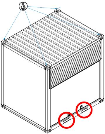
Lift container with a crane
Transportation with a crane is possible via the following three variants.
| Variant | Image | Notes |
|---|---|---|
1 |
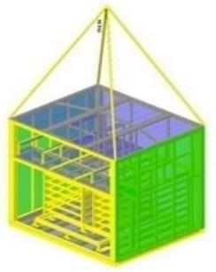
|
|
2 |
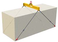
|
|
3 |
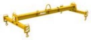
|
|
Declaration of batteries
Further information on the declaration of batteries can be found in the MSDS (Annex, Applicable documents).
9. Decommissioning and disassembly
9.1. Safety instructions — Disassembly
-
Wear the following suitable PPE for all work:
-
Protective footwear
-
Cut-resistant protective gloves
-
Protective eyewear
-
-
Cordon off a wide area around the system to be dismantled.
-
Dismantling work must only be carried out by qualified electricians/maintenance personnel.
-
Only carry out dismantling work when the system is shut down. Only trained personnel must carry out the work.
-
The power supply to the system is interrupted and secured against being switched on again.
-
Before starting disassembly, secure all components to be removed against falling, tipping over or moving.
-
Use transport aids. Use existing attachment points for transporting the system parts.
-
Observe the dismantling instructions by the component manufacturer (⇒ Appendix, Applicable documents).
-
Proceed from top to bottom when dismantling.
-
When transporting battery modules, the current laws, regulations and standards must be observed (e. g. Hazardous Goods Transportation Act — GGBefG).
-
The slide-in battery modules are removed by service personnel and transported by hazardous goods transport.
Residual risks:
|
||
|
||
|
9.2. Final decommissioning
9.2.1. Requirements - Final decommissioning
-
The system is switched off.
-
The power supply is interrupted and secured against being switched on again.
-
The operator’s information technology equipment has been dismantled and removed from the system.
-
The air conditioning unit is switched off.
-
The power supply to the air conditioning unit is interrupted and secured against being switched on again.
9.3. Recommended procedure — Disassembly
-
Disconnect the supply cable from the disconnecting device; first disconnect the power conductors, then the grounding cables.
-
Check that the power supplies are disconnected from the system and the air conditioning unit and that all systems are depressurized.
-
Empty all pipes and hoses and dispose of the contents in accordance with the regulations (⇒ section: Disposal).
-
Empty all refrigerant containers and dispose of liquids in accordance with regulations (⇒ section: Disposal).
-
Take the UPS out of operation.
-
Remove the fuse/bridge of the fire alarm system.
-
Remove the fuses from the Weidmüller devices.
-
Remove the RJ45 cable from the connection to the operator network.
-
Remove the RJ45 cable between the control cabinet and the energy meter.
-
Dismantle the Janitza devices.
-
Remove the AC connection.
-
Remove earthing.
-
Disconnect and remove the connection cable to the Wöhner device.
-
Remove the copper rings on the air conditioning hoses that serve as the connection between the battery and the cooling manifold.
-
Remove the C2C components.
-
Remove the grounding cable from the battery.
-
Remove the battery locking caps.
-
Place the HV cover cap on the batteries.
-
Remove the bolts from the batteries.
-
Remove the batteries using a forklift truck.
9.4. Disposal
|
After proper disassembly, recycle the dismantled individual parts:
-
The electrical energy storage system must not be disposed of with normal household waste.
-
Scrap metallic materials.
-
Have plastic elements recycled.
-
Dispose of the remaining components sorted according to material properties.
Electrical waste, electronic components, lubricants and other auxiliary materials are subject to hazardous waste treatment and must only be disposed of by authorized specialist companies.
Also observe the following points when disposing of the electrical energy storage system or its components as well as the operating and auxiliary materials:
-
Comply with local national regulations.
-
Observe company-specific specifications.
-
Dispose of operating and auxiliary materials in accordance with the applicable safety data sheets.
-
The packaging material must be disposed of in an environmentally friendly manner.
Batteries
-
Do not expose the battery modules to high temperatures or direct sunlight.
-
Do not expose the battery modules to high humidity or corrosive atmospheres.
-
For special instructions on the disposal of used batteries, please contact contact FENECON Service.
11. Register
11.1. Applicable documents
|
| No. | Component | Manufacturer documentation |
|---|---|---|
1 |
KACO blueplanet gridsave 92.0 kVa |
Available online: |
2 |
Climate control unit by Envicool |
Available online: |
3 |
EWON Cosy Router |
Available online: |
4 |
Container ESS10 — Circuit diagram |
FENECON GmbH |
5 |
Container ESS10 — List of wear and spare parts |
FENECON GmbH |
6 |
Container ESS10 — Declaration of Conformity (EU) |
FENECON GmbH |
7 |
Container ESS10 — Dimensioning of cables and wires |
FENECON GmbH |
8 |
FEMS — Technical Documentation |
FENECON GmbH |
9 |
HV Battery BEV SE09 — Safety Data Sheet |
BMW |
10 |
REFUstore 88k |
REFU Elektronik GmbH |
11 |
KACO gridsave 92 kVa |
KACO new energy GmbH |
12 |
Integrated climate control unit RFCS-SON-016000-C-L-R25-3-IW — Data sheet |
HYDAC INTERNAIONAL GmbH |
13 |
Coolant R-134a — Safety Data Sheet |
Westfalen AG |
14 |
Fire alarm system — Aspirating Smoke Detector (ASD) — Data sheet |
Hekatron Vertriebs GmbH |
15 |
Breaker RE-NA003 — Manual |
TELE Haase Steuergeräte GmbH |
16 |
Cable sealing — Installation Instruction |
Roxtec |