FENECON Automatic Off-Grid Switch (AVU)
Version: 2026.07.01
1. Version/revision
| Version/Revision | Change | Date | Name |
|---|---|---|---|
2026.2.1 |
Revision of the original automatic off-grid switch instructions |
February 15, 2026 |
FENECON PM |
2026.5.1 |
Note on clockwise rotating field |
04/05/2026 |
FENECON PM |
2026.07.01 |
Application of ISO warnings |
07/01/2026 |
FENECON PM (MRH) |
2. Note on the statutory warranty
The automatic off-grid switch is covered by the statutory warranty of 2 years, starting from receipt of the goods.

4. Structure of Warning Labels
When followed, warning notices help prevent potential injury and property damage, and the signal word indicates the severity of the hazard.
Warnings are structured according to the SAFE method:
| Signal Word | Meaning |
|---|---|
S |
Signal Word (DANGER, WARNING, CAUTION, or NOTICE) |
A |
(German: Art) — Type and source of the hazard |
F |
(German: Folge(n)) — Consequence |
E |
Escape |

|
DANGER |
|---|---|
5. Terms and abbreviations
The following terms and abbreviations are used in the assembly and service instructions:
| Term/Abbreviation | Meaning |
|---|---|
AC |
Alternating Current |
AVU |
Automatic off-grid switch |
BMS |
Battery Management System |
DC |
Direct Current |
EMS |
Energy Management System |
Energy Meter |
Electricity meter for the inverter at the grid connection point |
IBN |
Commissioning |
GCP |
Grid connection point |
PE |
Protective earth conductor |
VDE |
German Association for Electrical, Electronic & Information Technologies |
Widget |
Component of FENECON Online Monitoring |
6. Safety
6.1. Intended use
The automatic off-grid switch is a supplement to the electrical energy storage system.
It ensures automated, independent and all-pole switching of the entire household consumption from the mains supply to the emergency power output of the inverter (and back when the mains supply is restored). Manual switching from outside is also possible.
6.2. Qualification of staff
The system must only be installed and maintained by qualified personnel.
6.2.1. Qualified electricians
Qualified electricians include persons who
-
are able to carry out work on electrical systems due to their technical training, knowledge and experience, including knowledge of all relevant standards and regulations.
-
have been commissioned and trained by the operator to carry out work on electrical systems.
-
are familiar with how the automatic off-grid switch works.
-
recognize hazards and prevent them by taking appropriate protective measures.
6.3. General information about the automatic off-grid switch
-
Only qualified electricians are allowed to install the automatic off-grid switch and make cable connections.
-
The automatic off-grid switch must only be used under the specified conditions (see Technical data AVU-63-21).
-
Do not immerse the unit in water, moisten it or touch it with wet hands.
-
Maintain clearances to water sources.
-
Keep the automatic off-grid switch away from children and animals.
-
The automatic off-grid switch can cause electric shock and burns due to short-circuit currents.
-
Keep the automatic off-grid switch away from heat sources.
-
Do not use the automatic off-grid switch if color changes or mechanical damage are detected during assembly, normal operation and/or storage.
-
Do not set up or use the automatic off-grid switch near open flames, heaters or high-temperature sources.
-
The heat can cause insulation to melt.
-
Do not throw or drop the unit.
-
Read and adhere to the instructions for installation and operation in order to avoid damage due to incorrect operation.
-
Do not step on the unit.
6.3.1. Installation, operation and maintenance
Always observe the following safety instructions when installing, operating or maintaining the automatic off-grid switch:
-
Installation/maintenance work and making cable connections must only be carried out by qualified electricians.
-
Place on a dry, insulating mat and do not wear any metal objects (e. g. watches, rings and necklaces) during maintenance work/operation.
-
Use insulated tools and wear personal protective equipment (PPE).
-
Live contacts with a potential difference must not touch each other.
-
Measure the battery voltage with a multimeter and ensure that the output voltage is 0 V in Off Mode.
-
If an abnormality is detected, switch off the device immediately.
-
Only continue the maintenance work after the causes of the anomaly have been removed.
7. Technical data AVU-63-21
7.1. General
| Designation | Value/dimension | |
|---|---|---|
Installation/ |
IP classification |
IP20 |
Installation site |
Indoor |
|
Operating altitude above sea level |
≤ 2,000 m |
|
Overvoltage category (OVC) |
|| |
|
Protection class |
I (PE protective conductor) |
|
Max. Humidity |
95 % |
|
Installation/operating temperature |
-5 °C to +45 °C |
|
Grid connection |
L1, L2, L3, N, PE |
|
Fuse protection of grid connection |
63 A |
|
Residual current monitoring |
Observe requirements depending on installation location |
|
Rated frequency |
50 Hz to 60 Hz |
|
Output voltage AC |
400 V |
|
Max. Mains operation current |
63 A |
|
Suitable network configurations |
TN-S and TT |
|
Load connection |
L1, L2, L3, N |
|
Emergency power operation |
Apparent power emergency power operation |
15,000 VA |
Max. Current emergency power operation |
21.7 A |
|
Network configuration emergency power operation |
TN-S |
|
Switchover times |
Mains failure > Emergency power supply operation: approx. 3 s |
|
Certification/guideline |
Complete system |
CE |
General |
Width | Depth | Height in mm |
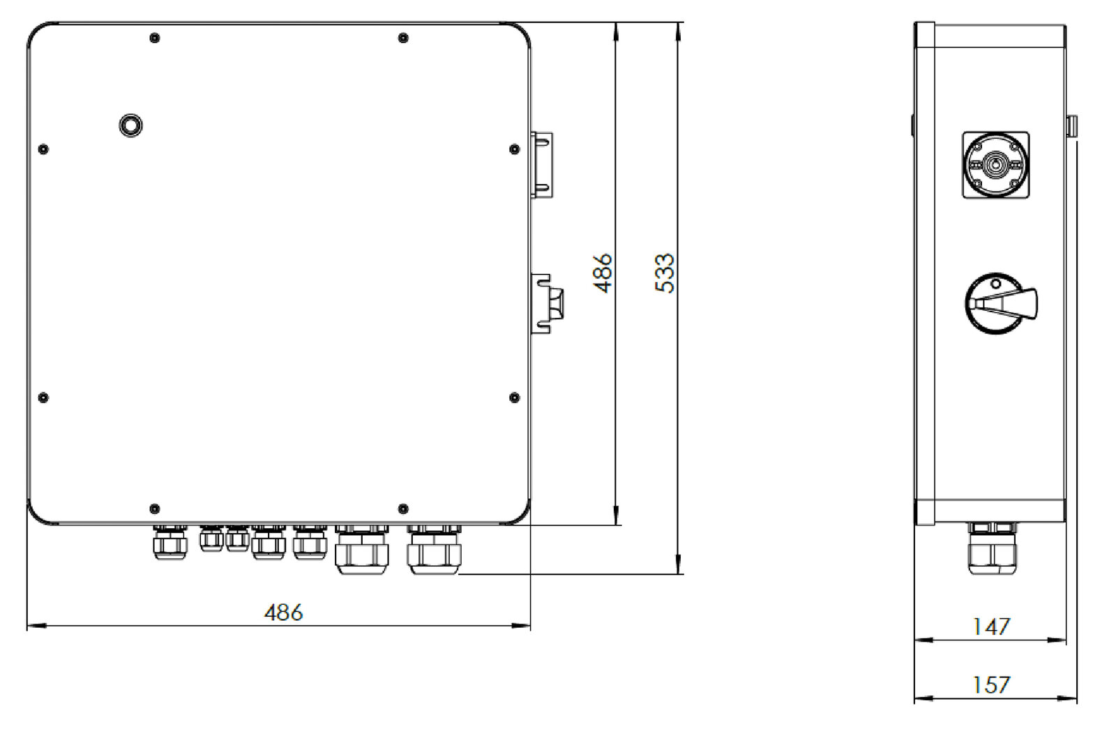
486 | 147 | 486 |
Weight, approx. |
16 kg |
|
Degree of soiling |
2 |
|
Mechanical force/impact resistance |
IK8 |
|
7.3. Terminal assignment
7.3.1. Overview — Interior
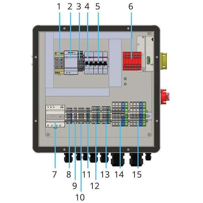
| List item | Description |
|---|---|
1 |
3-phase monitoring relay — incl. neutral monitoring |
2 |
DIN rail power supply unit 12 V/DC; 4.5 A; 54 W |
3 |
3 x fuse terminals (incl. fuse) + 1 x feed-through terminal |
4 |
Automatic circuit breaker: C6 miniature circuit breaker; 1-pole |
5 |
Automatic circuit breaker: C32 miniature circuit breaker, 4-pole |
6 |
Gave motorized switch (automatic off-grid switch) |
7 |
Optional: FENECON Home 10 energy meter |
8 |
Feed-through terminal blocks for the power supply of the energy meter |
9 |
Feed-through terminal blocks Internal power supply (12 V) |
10 |
Feed-through terminal blocks for connection to the relay — for LED status query |
11 |
Feed-through terminal blocks for the power supply to the EMS box |
12 |
Feed-through terminals for connecting to the inverter — OnGrid/grid |
13 |
Feed-through terminal blocks for connection to the inverter — OffGrid/emergency power |
14 |
Feed-through terminal block for grid connection |
15 |
Feed-through terminal blocks for connecting consumer loads |
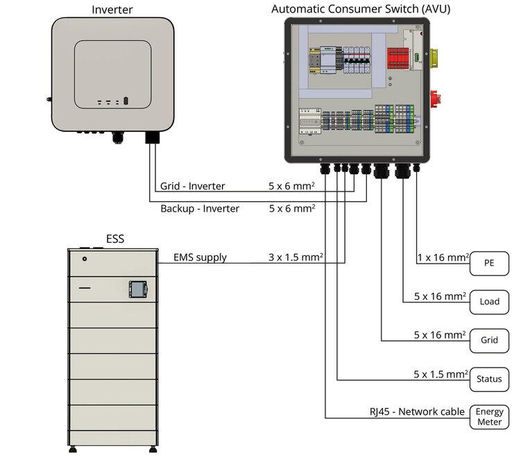
7.3.2. Detailed terminal assignment

| List item | Description |
|---|---|
X16 |
Optional: Supply FENECON Home 10 energy meter |
X12 |
12 V DC |
X10 |
Relay status |
X6 |
AC supply — EMS box |
X4 |
Inverter — Grid |
X5 |
Inverter — Off-Grid |
X1 |
Grid connection |
X7 |
Load connection |
8. General description
The automatic off-grid switch is a supplement to an electrical energy storage system. The unit allows for an unrestricted supply of the consumer loads with max. 43 kW or 63 A in parallel mains operation.
The automatic off-grid switch ensures automated, independent switching of the entire household consumption from the grid supply to the emergency power output of the inverter and back when the grid is restored. Manual switching is also possible. For the installation of the storage system, please follow the instructions of the respective system found here: docs.fenecon.de/en!
|
The compliant grid disconnection still takes place in the inverter. The automatic off-grid switch is used exclusively for switching the consumer loads. |
9. Assembly preparation
9.1. Scope of delivery
The following items are included in the scope of delivery.
| Image | Amount | Description |
|---|---|---|
|
1 |
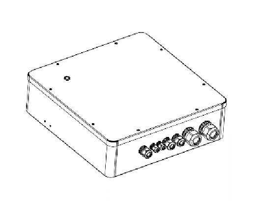
Automatic off-grid switch |

|
1 |
Wall bracket |

|
2 |
Screw for wall mount |

|
4 |
M6 x 67 mm screw and 8 x 60 mm screw anchor for wall mounting |

|
1 |
Nut, body washer and spring washer for earthing |

|
2 |
Filler plug for unused bolt connections |

|
1 |
Assembly and operating instructions |
9.2. Tools required
The following tools are required for assembly of the system components:
| Image | Description | Image | Description |
|---|---|---|---|

|
Pencil |

|
Spirit level |

|
Impact drill or |

|
Screwdriver set |

|
Meter stick |

|
Side cutter |

|
Allen key, 3 mm |

|
Set of flat spanners |

|
Crimping tool |

|
Multimeter |

|
Pliers for cable glands |

|
Protective eyewear |

|
Safety footwear |

|
Dust mask |

|
Rubber mallet |

|
Vacuum cleaner |

|
Wire stripper |

|
Protective gloves |

|
Torque wrench |

|
Stripping knife |
|
The tool is not included in the scope of delivery. |
10. Assembly — Automatic Off-grid Switch
Before installation, carefully check whether the packaging and the product are damaged and whether all accessories listed in the scope of delivery are included. In the event that accessories are missing or damaged, contact the manufacturer/dealer.
10.1. Warnings and Safety Instructions
|
DANGER |
|---|---|
|
|
DANGER |
|---|---|

|
DANGER |
|---|---|
|
|
DANGER |
|---|---|

|
DANGER |
|---|---|
|
|
WARNING |
|---|---|
|
|
CAUTION |
|---|---|

|
NOTICE |
|---|---|
|
|
NOTICE |
|---|---|
|
|
NOTICE |
|---|---|
10.2. Pictograms
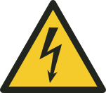
Pictograms on the system indicate dangers, prohibitions and instructions. Illegible or missing pictograms must be replaced by new ones.
| Pictogram | Meaning | Description |
|---|---|---|
|
|
Warning: Dangerous Electrical Voltage |
Pictogram on the housing and labeling of components where it is not immediately apparent that they contain electrical equipment that could pose a risk of electric shock. |
|
|
General warning symbol |
|

|
Warning Regarding Hazards Associated with Battery Charging |
Pictogram on the housing and labeling of components where it is not immediately apparent that they contain electrical equipment that could pose a risk due to battery charging. |

|
No open flames; Fire, open ignition sources, and smoking prohibited |
Pictogram on the housing and labeling of components where it is not immediately apparent that they contain electrical equipment that could pose a risk due to open flames, fire, open ignition sources, and smoking. |

|
Protective grounding symbol |
|

|
Separate Collection of Electrical and Electronic Equipment |
|

|
Follow instructions |
|

|
Use protective headgear |
|

|
Use protective footwear |
|

|
Use protective gloves |
|

|
CE mark |
|

|
Product is recyclable. |
10.3. Operating materials/equipment
10.3.1. Electrolyte solution of the battery modules
-
Electrolyte solution is used in the battery modules (lithium iron phosphate).
-
The electrolyte solution in the battery modules is a clear liquid and has a characteristic odor of organic solvents.
-
The electrolyte solution is flammable.
-
The electrolyte solution in the battery modules is corrosive.
-
Contact with electrolyte solution can cause severe burns to the skin and damage to the eyes.
-
Do not inhale the vapors.
-
If the electrolyte solution is swallowed, induce vomiting.
-
Leave the contaminated area immediately after inhaling the vapors.
-
Eye and skin contact with leaked electrolyte solution must be avoided.
-
After skin contact: Immediately wash skin thoroughly with neutralizing soap and consult a doctor if skin irritation persists.
-
After eye contact: Immediately flush eye(s) with running water for 15 minutes and seek medical advice.
-
Delayed treatment can cause serious damage to health.
10.3.2. Electrical equipment
-
Work on electrical equipment must only be carried out by qualified electricians.
-
The five safety rules must be observed for all work on electrical components:
-
Disconnect.
-
Secure against restarting.
-
Check that there is no voltage.
-
Earth and short-circuit.
-
Cover or shield neighboring live parts.
-
-
Maintenance work must only be carried out by trained specialist personnel (service personnel).
-
Before starting work, carry out visual checks for insulation and housing damage.
-
The system must never be operated with faulty or non-operational electrical connections.
-
To avoid damage, lay supply lines without crushing and shearing points.
-
Only insulated tools must be used for maintenance on uninsulated conductors and terminals.
-
Control cabinets (e. g. inverter housing) must always be kept locked. Only authorized personnel with appropriate training and safety instructions (e. g. service personnel) should be allowed access.
-
The inspection and maintenance intervals for electrical components specified by the manufacturer must be observed.
-
To avoid damage, lay supply lines without crushing and shearing points
-
If the power supply is disconnected, specially marked external circuits may still be live!
-
Some equipment (e. g. inverters) with an electrical intermediate circuit may still carry dangerous residual voltages for a certain period of time after disconnection. Before starting work on these systems, check that they are de-energized.
10.4. Personal protective equipment
Depending on the work on the system, personal protective equipment must be worn:
-
Protective footwear
-
Protective gloves, cut-resistant if necessary
-
Protective eyewear
-
Protective headgear
10.5. Spare and wear parts
The use of spare and wear parts from third-party manufacturers can lead to risks. Only original parts or spare and wear parts approved by the manufacturer must be used. The instructions for spare parts must be observed. Further information can be found in the wiring diagram.
|
Further information must be requested from the manufacturer. |
10.6. IT security
FENECON systems and their applications communicate and operate without an internet connection. The individual system components (inverters, batteries, etc.) are not directly connected to the internet or accessible from the Internet. Sensitive communications via the internet are processed exclusively via certificate-based TLS encryption.
Access to the programming levels is not barrier-free and is accessible at different levels depending on the qualifications of the operating personnel. Safety-relevant program changes require additional verification.
FENECON processes energy data of European customers exclusively on servers in Germany and these are subject to the data protection regulations applicable in this country.
The software used is checked using automated tools and processes established during development in order to keep it up to date and to rectify security-relevant vulnerabilities at short notice. Updates for FEMS are provided free of charge for life.
10.7. Installation conditions and clearances at the installation site

Installation conditions
-
The wall must be stable enough for mounting the automatic off-grid switch and must not be flammable.
-
The room should be permanently ventilated.
-
Maintain a clearance of at least 300 mm above the automatic off-grid switch.
-
Maintain a clearance of at least 300 mm below the automatic off-grid switch (cable ducts are not measured here).
-
Maintain a clearance of at least 1000 mm from the front of the automatic off-grid switch.
-
Keep at least 100 mm clearance to the left of the automatic off-grid switch.
-
Maintain a clearance of at least 400 mm to the right of the automatic off-grid switch.
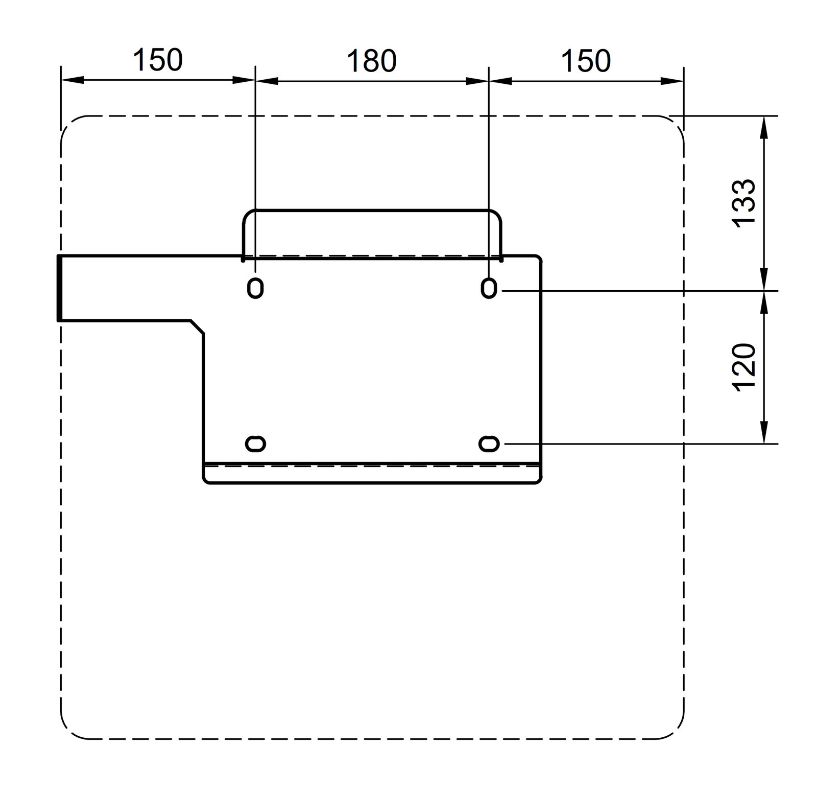
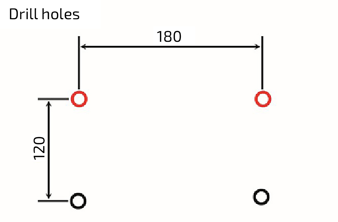
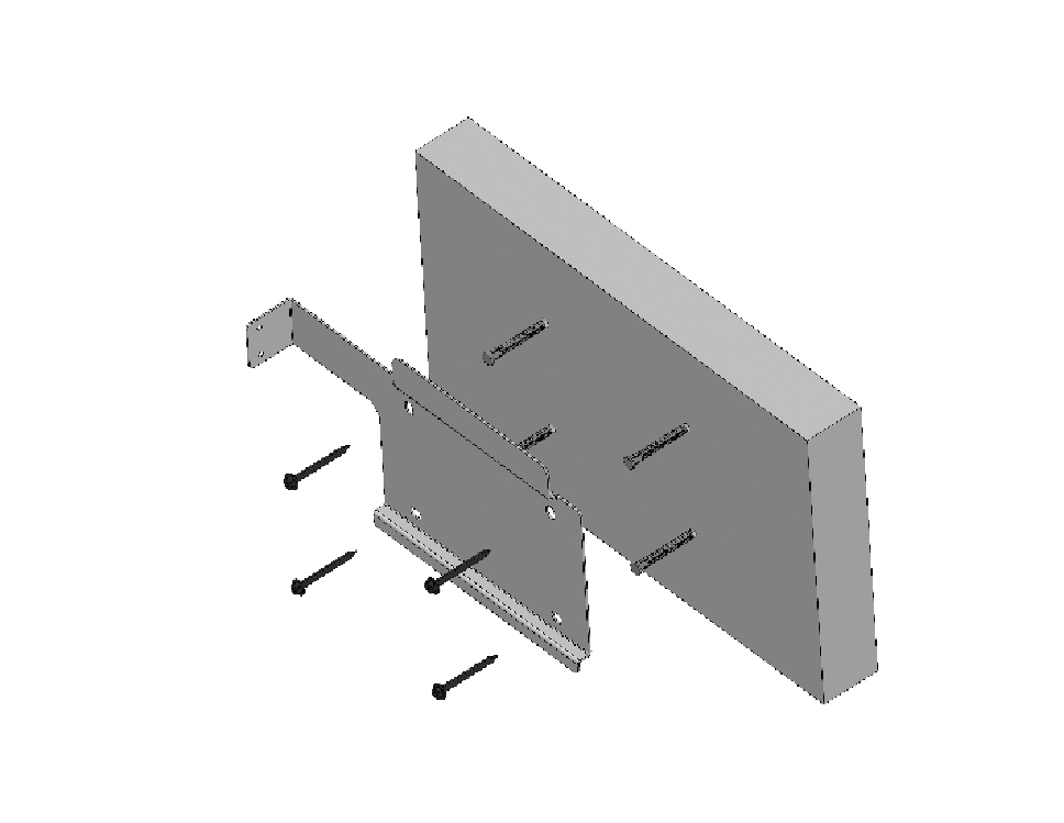
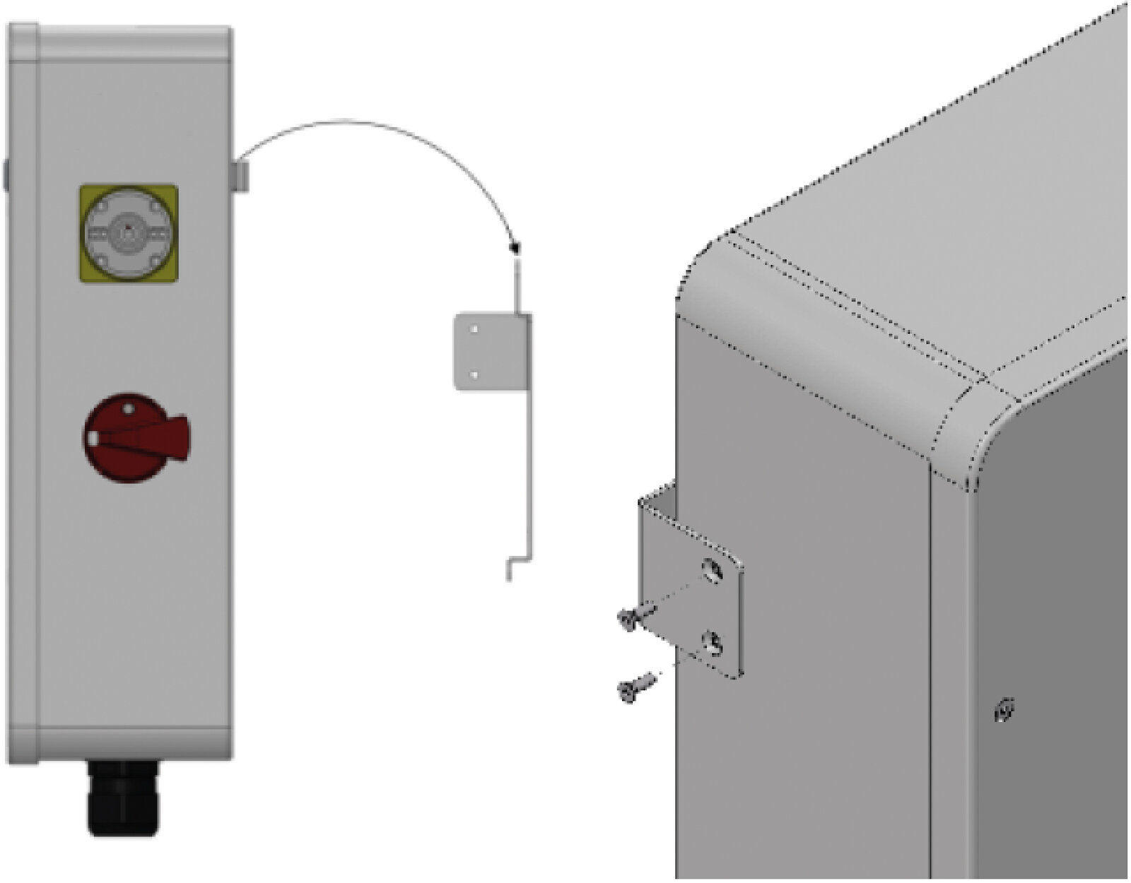
10.8. Wall mounting
Proceed as follows to install the automatic off-grid switch on a wall:
Assembly of the wall bracket
|
|
|
|
|
|
|
|
|
|
11. Electrical installation
11.1. Overview of the connections
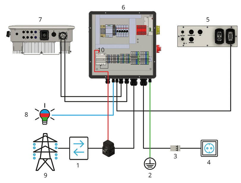
| List item | Description |
|---|---|
1 |
Bi-directional meter from energy supplier |
2 |
Earth circuit connector or earthing connection |
3 |
Fuse protection of the consumer loads with RCD type A and suitable MCBs |
4 |
Consumer loads/emergency power consumers |
5 |
EMS box connection (uninterruptible) (AC supply to the EMS box) |
6 |
Automatic off-grid switch (AVU) |
7 |
Inverter |
8 |
External status signal |
9 |
Grid |
10 |
Optional: FENECON Home 10 energy meter (energy flow direction meter) |
|
Clockwise rotating field mandatory Before installation, use a two-pole voltage tester to check whether a clockwise rotating field is present. |
|
Between positions 1 and 6:
|
|
Optional earthing connection: |
11.2. Connection between the individual components
11.2.1. Connection to the inverter
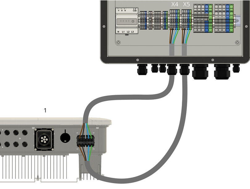
| List item | Description |
|---|---|
1 |
Inverter |
X4 |
Grid connection inverter to X4 (on-grid) (5 x 4 mm2) |
X5 |
Emergency power connection inverter to X5 (OFF-Grid) (5 x 4 mm2) |
11.2.2. Connection to the EMS box
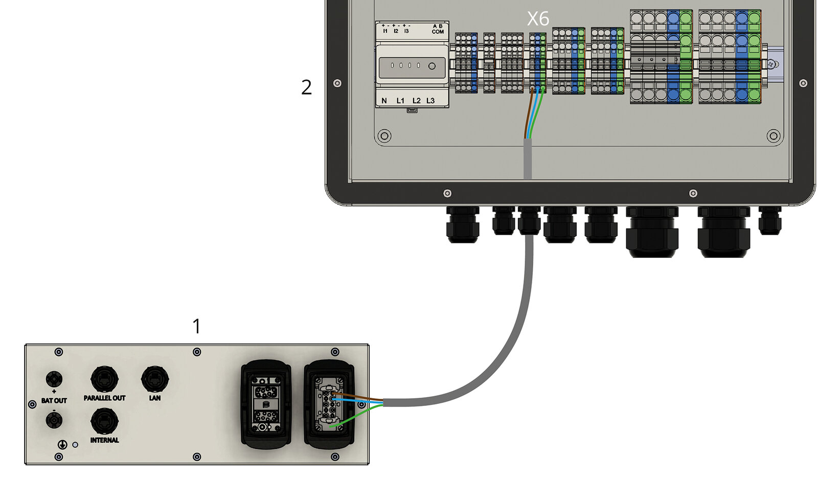
| List item | Description |
|---|---|
1 |
EMS box (AC connection) |
X6 |
AC supply connection — EMS box to X6 (3 x 1.5 mm2) |
11.2.3. Energy meter connection without external generators

| List item | Description |
|---|---|
1 |
Grid |
2 |
Bi-directional meter of the energy supply company (grid operator) |
3 |
Power supply from energy meter X16 (4 x 1.5 mm2) |
4 |
Split-core CT (directly behind the grid operator’s meter) already pre-assembled on the Energy Meter |
5 |
Inverter |
6 |
Modbus connection between Energy Meter and inverter |
|
If you have an existing system with an Energy Meter already installed, the Energy Meter does not need to be modified. |
11.2.4. Connection of an external status display (optional)
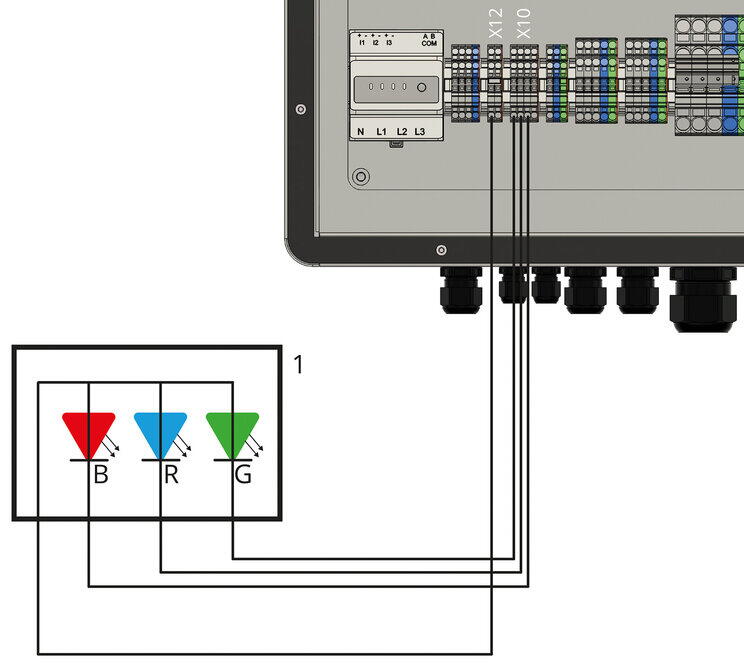
| List item | Description |
|---|---|
1 |
External status display (three states, each state: 12 V DC/100 mA) |
|
The external status display is a separate installation by the installer. |
11.3. Electrical installation with external AC generator
11.3.1. Overview of the connections

| List item | Description |
|---|---|
1 |
Bi-directional meter of the energy supply company (grid operator) |
2 |
Earth circuit connector or earthing connection |
3 |
Fuse protection of the consumer loads with RCD type A and suitable MCBs |
4 |
Consumer loads/emergency power consumers |
5 |
EMS box connection (uninterruptible) (AC supply to the EMS box) |
6 |
Automatic off-grid switch (AVU) |
7 |
Inverter |
8 |
External status signal |
9 |
Grid |
10 |
FENECON Home 10-Energy meter (energy flow direction meter) |
11 |
External AC generator |
|
PV inverters, CHP units, small wind turbines or other generators in the existing sub-distribution board must be installed at point 11. |
11.3.2. Energy meter connection with external AC generator
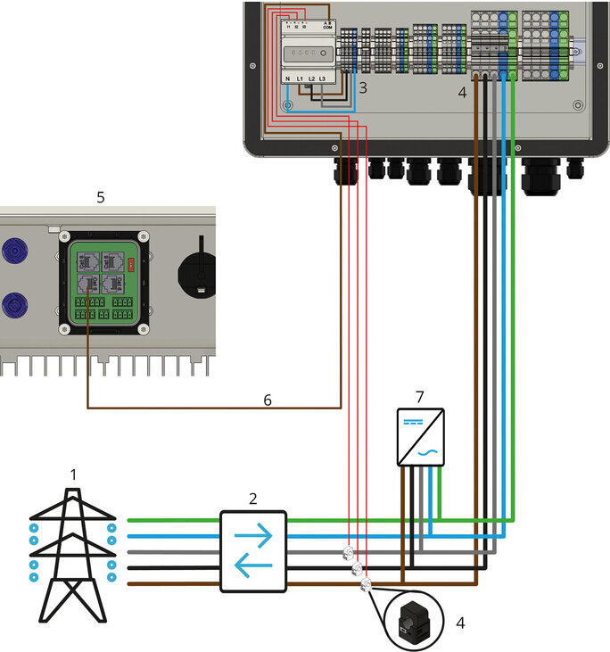
| List item | Description |
|---|---|
1 |
Grid |
2 |
Bi-directional meter of the energy supply company (grid operator) |
3 |
FENECON Home 10 Energy meter (voltage supply from X16: 4 x 1.5 mm2) |
4 |
Split-core CT (directly behind AC generator) already pre-assembled on the smart meter |
5 |
FENECON Inverter |
6 |
Modbus between Smart Meter and FENECON inverter |
7 |
AC generator (directly behind the grid operator’s meter and behind the split-core CTs of the energy meter) |
|
If you have an existing system with an Energy Meter already installed, the Energy Meter does not need to be modified. |
12. Display and operation
12.1. LED status display
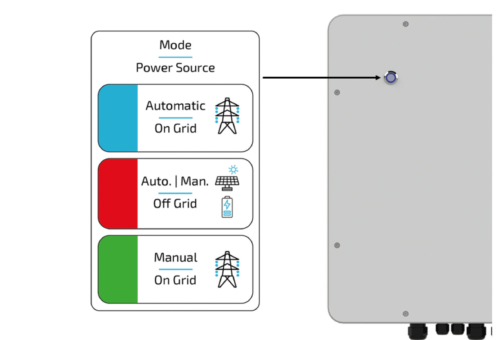
| List item | Description |
|---|---|
Blue |
The system is in automatic mains operation |
Red |
The system is in emergency power mode (automatic/manual) |
Green |
The system is in manual mains operation |
12.2. Operating activities
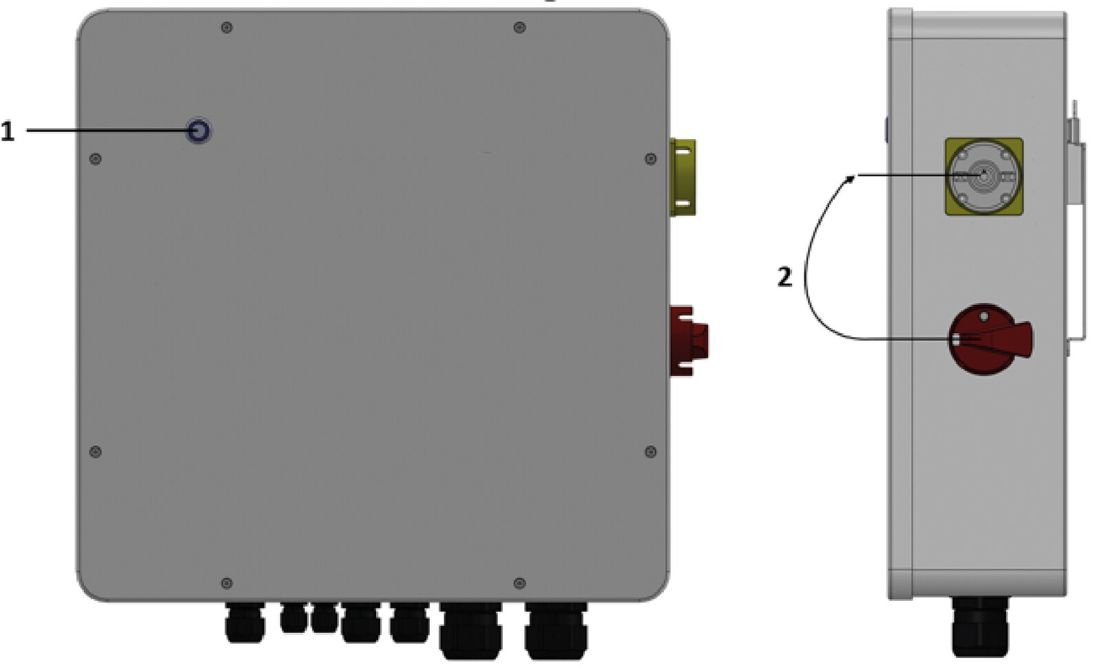
| List item | Switch position | Description |
|---|---|---|
1 |
Press LED switch |
Motor in switch 2 is switched off (LED lights up green) |
2 |
Put on switch and turn |
The mode can be changed manually. |
13. Initial commissioning
13.1. Checking the installation, connections and cabling
Check the system as follows before initial commissioning:
-
All components (clearances, environment, mounting) are installed correctly.
-
All internal wiring is complete and properly connected.
-
All external supply lines (power supply, communication cable) are properly connected.
-
All connected loads are matched to the system and the necessary settings have been made.
-
All necessary tests of the system were carried out in accordance with the standards.
13.2. Settings on the monitoring relay
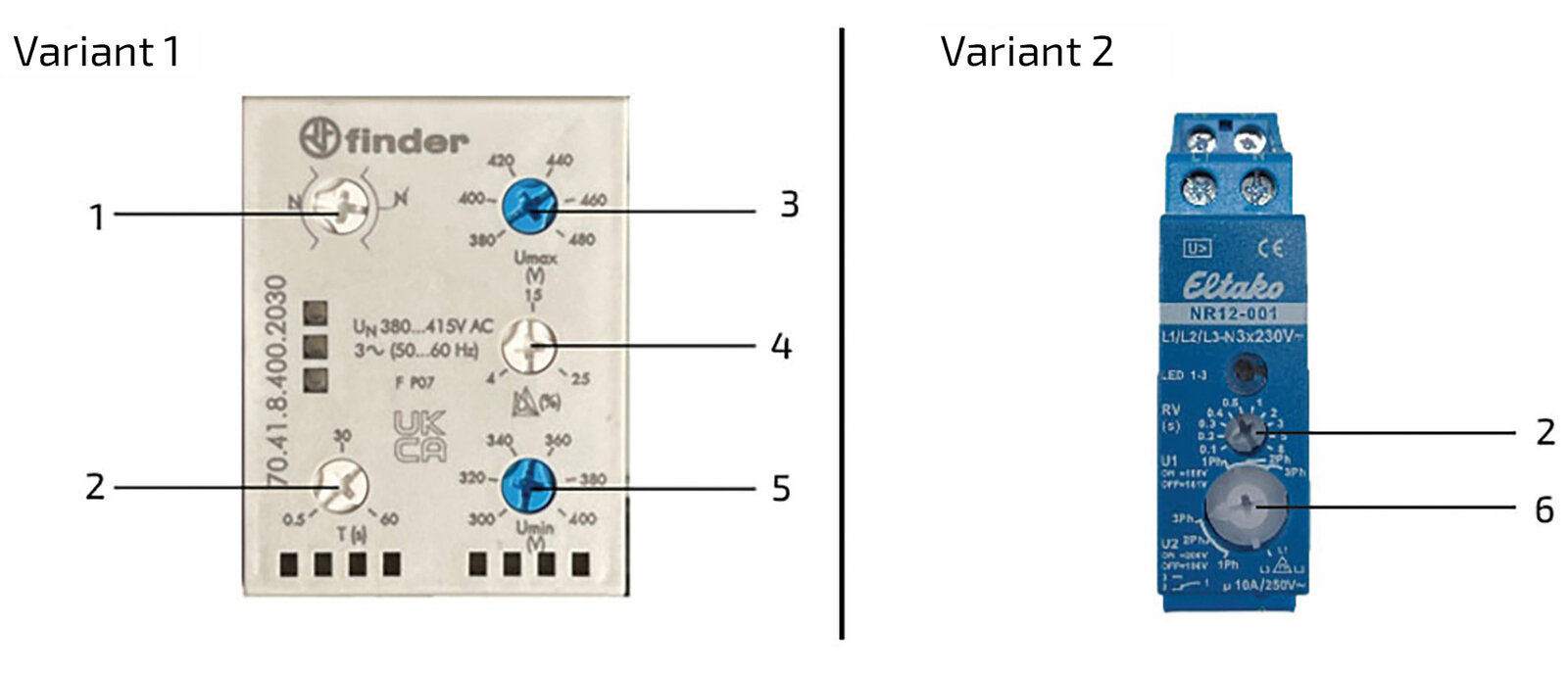
| List item | Description |
|---|---|
1 |
Neutral monitoring (with or without) Setpoint: With neutral |
2 |
Switch-off delay (between 0.5 and 60 seconds) Setpoint: 0.5 seconds or 0.1 seconds |
3 |
Maximum voltage (between 380 and 480 V) Setpoint: 450 V |
4 |
Nominal voltage (between 4 and 25 %) Setpoint: 15 % |
5 |
Minimum voltage (between 300 and 400 V) Setpoint: 350 V |
6 |
Rotary function switch for various pick-up and drop-out voltages Setpoint: U2 - 3Ph |
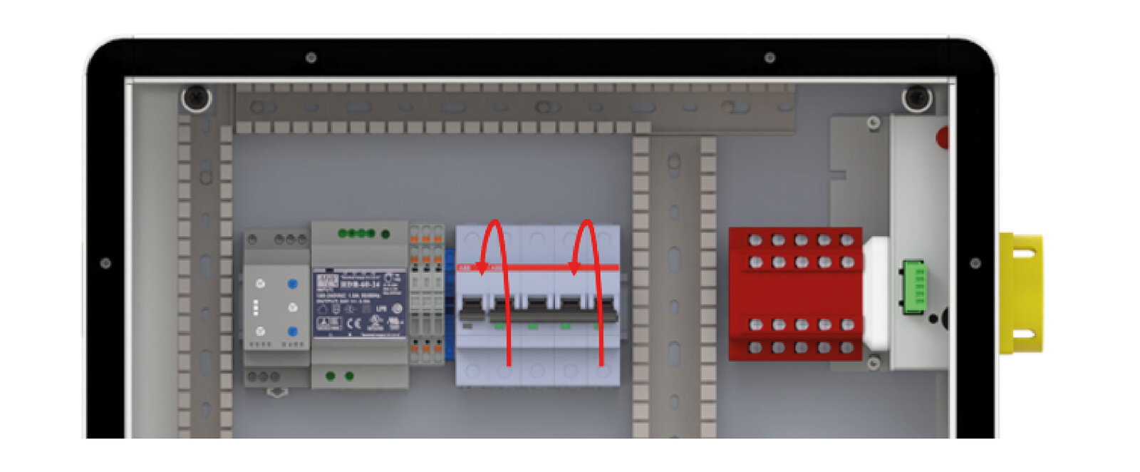
13.3. Switching on the miniature circuit breakers
The miniature circuit breakers in the automatic off-grid switch must then be switched on.
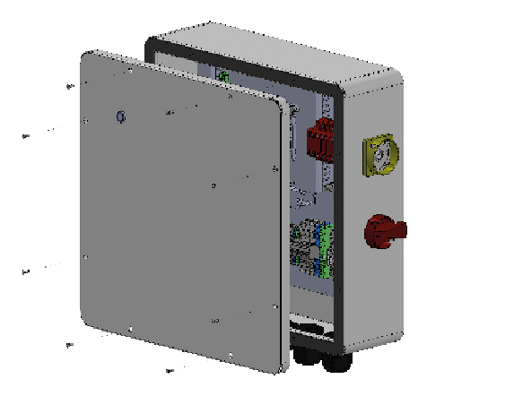
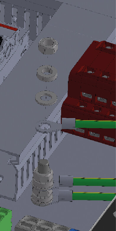
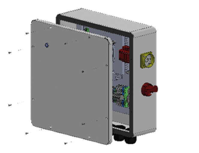
13.4. Final assembly
Proceed as follows for final assembly of the automatic off-grid switch:
Installation of the cover

|
|
|
|
|
|
13.5. Switching the system on/off
13.5.1. Switch on
The system must be switched on in the following order:
-
Switch on the main fuse.
-
Switch on the inverter.
-
Switch the battery energy storage system.
-
Check whether the push-button is set to automatic mode.
The automatic off-grid switch now automatically switches to grid operation when the grid is connected.
|
If back-up power has not yet been activated on the Home system, the commissioning must be performed again to activate the back-up power function. |
13.5.2. Switching off
If the system must be taken out of operation, please proceed in the following order:
-
Switch off the battery energy storage system.
-
Switch off the inverter.
-
Switch off the main fuse on the meter.
-
Switch off the circuit breaker in the automatic off-grid switch.
Make sure the device is de-energized before dismantling or modifying it!
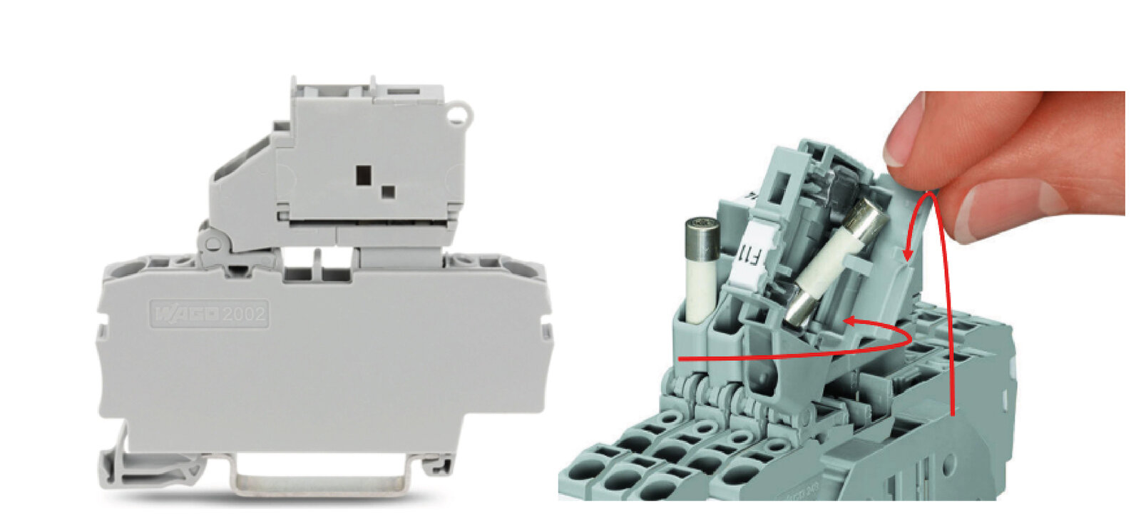
13.6. Replacing the cartridge fuses
If a cartridge fuse is defective, it must be replaced as shown in the following image.
|
|
DANGER |
|---|---|
|
Only cartridge fuses, medium time delay (250 V/6.3 A), are to be used! (Littlefuse 021506.3) |
Electrical data
Materials |
Housing: |
Clamping strength |
MIL-STD-202, method 211, test condition A |
Solderability |
MIL-STD-202 Method 208 |
Marking of the product |
Cable 1: Brand logo, current and voltage values Cable 2: Test seal |
Operating temperature |
-55 °C to +125 °C |
Thermal shock test |
MIL-STD-202, method 107, test condition B (5 cycles, -65 °C to +125 °C) |
Vibration test |
MIL-STD-202, method 201 |
Humidity test |
MIL-STD-202, method 103, test condition A (high humidity (95 %) and elevated temperature (40 °C) for 240 hours) |
Salt spray test |
MIL-STD-202, method 101, test condition B |
14. FENECON Service
If the system malfunctions, contact FENECON Service:
Phone: +49 (0) 9903 6280 0
E-mail: service@fenecon.de
Our service hours:
Mon. to Thurs.: 8 a.m. to 12 p.m. | 1 p.m. to 5 p.m.
Fri.: 8 a.m. to 12 p.m. | 1 p.m. to 3 p.m.