Customer Interfaces Industrial M (452-904 kWh) IMK120/IMK220/IMK320
Rev. 01 — 30/09/2026
Version history
| Name | Revision | Datum | Bemerkung |
|---|---|---|---|
Christina Zehntner |
REV00 |
25.05.26 |
Erstellt |
Markus Aufschläger |
REV00 |
26.05.26 |
Freigegeben |
Christina Zehntner |
REV01 |
23.09.26 |
Erstellt |
Markus Aufschläger |
REV01 |
30.09.26 |
Freigegeben |
© FENECON GmbH, 2026 — All rights reserved.
Reproduction, even in part, is only permitted with the written consent of FENECON GmbH.
1. Customer interfaces
The FENECON Industrial M must have connections to the customer’s system via the interfaces listed below. Cables are fed in from the bottom or front via cable glands (Wiska ESKV EN62444).
1.1. Kabeleinführung
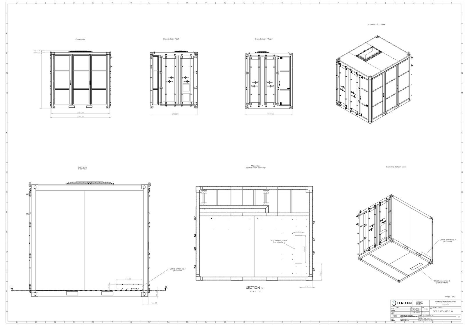
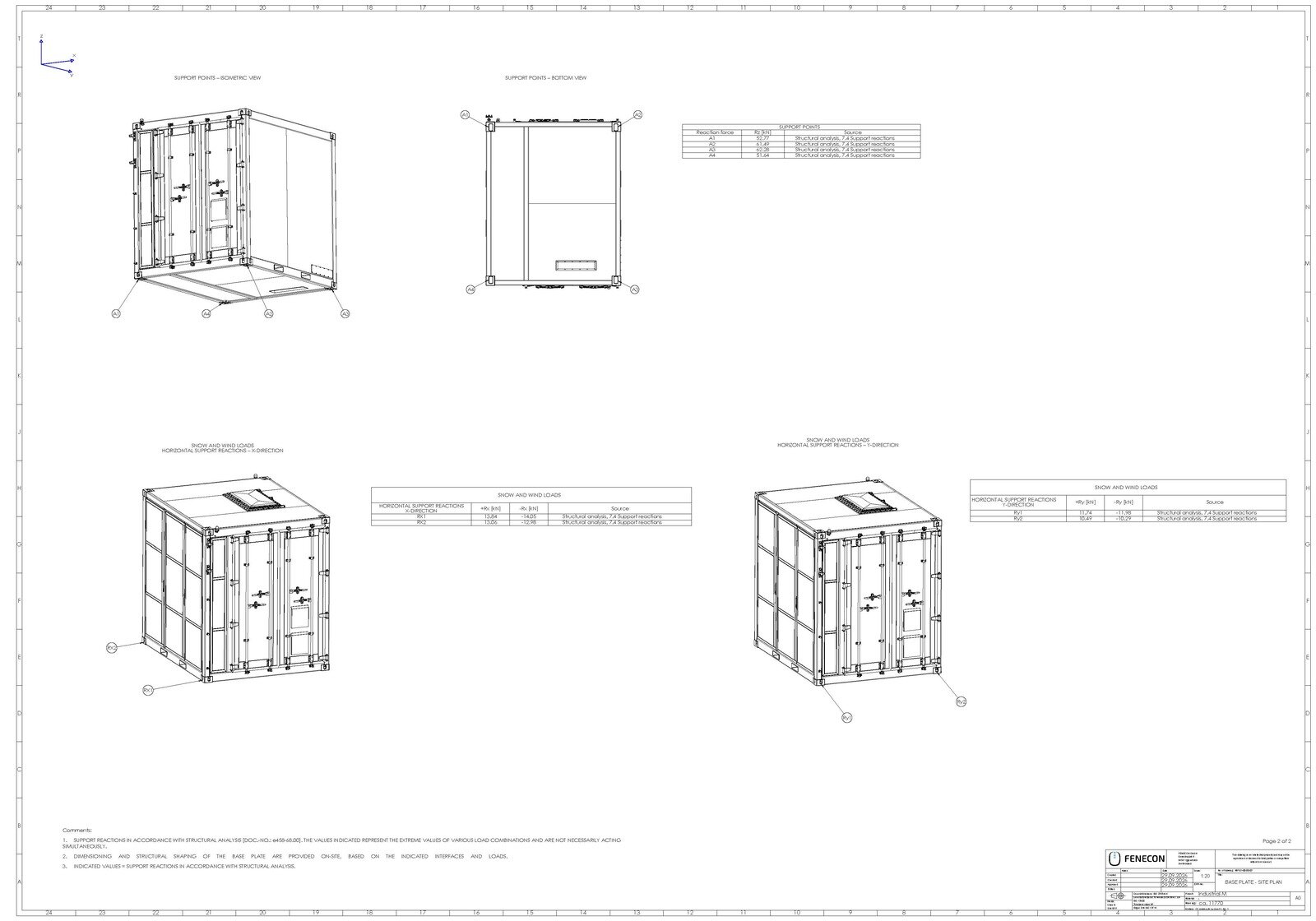
Die Kabeleinführung erfolgt boden- oder frontseitig über eine Kabeleinführungsplatte mit den Kabelverschraubungen aus Tabelle 1, s. Anhang A Fundament-Aufstellplan für die genaue Positionierung.
Die Verwendung der Platte ist zwingend notwendig. Durch die Nichtverwendung kann Schmutz und Feuchtigkeit eindringen und die Elektronik beschädigen! Nicht verwendete Kabeldurchführungen müssen mit Blindstopfen verschlossen werden!
| Beschreibung | Kabel (Beispiel) | Kabeldurchführung | Klemmbereich | Anzahl |
|---|---|---|---|---|
Kundenabhängig, |
10065006 EMSKV 50 |
21 mm bis 35 mm |
15 |
|
Externe Hilfsversorgung (optional) |
5G16 z. B. H07RN-F |
10065006 EMSKV 50 |
21 mm bis 35 mm |
1 |
Abschaltung Kunde |
2 x 1 z. B. Ölflex Classic |
10065000 EMSKV 16 |
4,5 mm bis 10 mm |
1 |
Modbus RTU/externer Zähler |
BUS-Kabel für Zähler am NAP |
10065000 EMSKV 16 |
4,5 mm bis 10 mm |
1 |
BMZ Feuer-, Gasalarm und Error |
7G1, z. B. Ölflex Classic |
10065002 EMSKV 20 |
6 mm bis 13 mm |
1 |
Internetanschluss |
Ethernet-Kabel oder Glasfaser |
10065002 EMSKV 20 |
6 mm bis 13 mm |
1 |
Externer Schreibzugriff |
Ethernet-Kabel für externen Schreibzugriff |
10065002 EMSKV 20 |
6 mm bis 13 mm |
1 |
1.2. Electrical power connection
Es sind 2-4 Stück des Wechselrichters KACO gridsave 92 TL3 verbaut. Diese sind AC-seitig über die integrierte NSHV verbunden und werden über den Kompaktleistungsschalter (Siemens 3VA2780-2AC06-4BB1) mit der Kundenanlage verbunden. Der Leistungsschalter verfügt über frontseitige, verbreiterte Hauptanschlüsse mit M12-Bohrungen.
Die Kabeldimensionierung erfolgt abhängig von den projektspezifischen Verlegebedingungen nach entsprechenden Normen. Für den Anschluss müssen VDE-AR-N 4110 und VDE-AR-N 4105 beachtet werden. Die vorhandenen Anschlussmöglichkeiten sind in Tabelle 2 dargestellt.
| Leiter | Anschlussstelle | Anschlussmittel | Anschlussquerschnitt | Anzugsdrehmoment |
|---|---|---|---|---|
L1, L2, L3 |
Leistungsschalter |
Rohrkabelschuh M12 |
120 bis 300 mm2 |
40 Nm |
N |
N-Schiene |
Sammelschienenklemme, |
95 bis 300 mm2 |
30 Nm |
PE |
PE-Schiene |
Sammelschienenklemme, |
95 bis 300 mm2 |
30 Nm |
Bei PE- und N-Leiter sind nicht zwingend die gleichen Querschnitte wie bei den Phasen notwendig. Es reicht auch jeweils der halbe Querschnitt aus. Die Dimensionierung ist gemäß den lokal vorherrschenden Bestimmungen zu wählen! Empfohlene Leitungsquerschnitte sind in Tabelle 3 dargestellt und gelten für Kupferleitungen. Die Querschnitte müssen je nach örtlichen Gegebenheiten (Absicherung, Leitungslänge, Verlegeart, Kabelhäufung, …) nach entsprechenden Normen berechnet werden.
| Ausbaustufe | Anschlüsse der Versorgung | Leiterquerschnitt |
|---|---|---|
Vier Wechselrichter |
L1, L2, L3 |
2 x 300 mm2 oder 3 x 150 mm2 |
N |
1 x 300 mm2 oder 2 x 150 mm2 oder 25 mm2 |
|
PE |
1 x 300 mm2 oder 2 x 150 mm2 |
|
Drei Wechselrichter |
L1, L2, L3 |
2 x 240 mm2 oder 3 x 120 mm2 |
N |
1 x 240 mm2 oder 2 x 120 mm2 oder 25 mm2 |
|
PE |
1 x 240 mm2 oder 25 mm2 |
|
Zwei Wechselrichter |
L1, L2, L3 |
1 x 300 mm2 oder 2 x 120 mm2 |
N |
1 x 150 mm2 oder 1 x 120 mm2 oder 25 mm2 |
|
PE |
1 x 150 mm2 oder 1 x 120 mm2 |
Da über den Neutralleiter lediglich der Strom für die Steuerungssysteme (max. 63 A) fließt, kann der Leiterquerschnitt im Vergleich zu den aktiven Leitern geringer ausfallen. Eine Reduzierung auf 25 mm2 muss nach DIN VDE 0100-520 Abschnitt 524.2.3 bewertet werden.
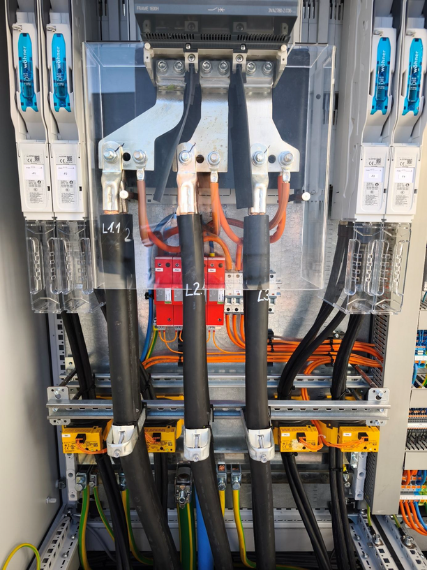
Abbildung 1 zeigt den fertigen Anschluss beispielhaft mit 2 x 300-mm2-Leitungen.
1.3. Utility connection
The Industrial M control cabinet is powered at terminal -X2 via the power connection on the circuit breaker. An alternative power supply can be provided by the customer. To do this, the jumper between -X1 and -X2 must be removed, and the customer’s power supply must be connected to -X1. Upon initial delivery, an external CEE plug is attached to -X1, which can be used to power the air conditioning during storage. This plug is removed during commissioning and replaced with the jumper from -X1 to -X2. Cables are routed through M50 cable glands at the bottom or front of the enclosure. A cable cross-section of 10–16 mm2 is recommended.
1.4. Grounding and Lightning Protection
Alle Komponenten müssen über die entsprechenden Erdungsfahnen an einen entsprechenden Potentialausgleich angeschlossen werden. Das Gesamtsystem ist in das örtliche Blitzschutzkonzept einzubinden. Der Leistungsanschluss ist standardmäßig mit einem Typ-1- und Typ-2-Überspannungsschutz ausgestattet. Der Anschluss für die Steuerelektronik ist zusätzlich mit einem Typ-1- und Typ-2-Überspannungsschutz ausgestattet. Die energetisch koordinierte Schutzwirkung zum Endgerät ist Typ 1 + Typ 2 + Typ 3.
1.5. Internet connection
Das System kann über Lichtwellenleiter (LWL) oder RJ45 an das Internet angeschlossen werden. Dafür muss eine entsprechende Leitung mit SFP+-Adapter an den verbauten Router angeschlossen werden. Die Auswahl hängt von der Länge der Leitung zum Kundenanschluss ab.
1.6. Externe Ansteuerung
The system can be connected to the higher-level control system (e. g. EMS, SCADA, parking controller, etc.) via a Modbus-TCP connection (RJ45) to receive power commands.
1.7. Fire detection system connections (optional)
Optional können die Kontakte der Brandmeldeanlage verwendet werden, um beispielsweise auf eine Brandmeldezentrale aufgelegt zu werden. Es stehen drei potenzialfreie Kontakte zur Verfügung (Voralarm, Hauptalarm und Störung), s. Beschreibung in Tabelle 4.
| Alarmtyp | Beschreibung | Kontaktart |
|---|---|---|
Gasalarm |
Es werden brennbare Gase im Container erkannt und die Belüftung aktiviert. |
Potenzialfreier Kontakt (Öffner) |
Feueralarm |
Es wurde ein Feuer erkannt. |
Potenzialfreier Kontakt (Öffner) |
Error |
Es wurde ein Fehler im Meldesystem erkannt. |
Potenzialfreier Kontakt (Öffner) |