Info sheet: Fire Alarm System for Industrial L
Industrial L from Rev. AA5
Starting with Rev. AA5, the Industrial L is available with an interface for integrating a fire detection system:
Item no. |
Description |
|---|---|
ILK710 |
FENECON Industrial L KACO with 736 kW and 1,288 kWh, on-site battery installation |
Industrial L with integrated fire detection system
The fire detection system is already installed at the factory:
Item no. |
Description |
|---|---|
ILK711 |
FENECON Industrial L KACO with 736 kW and 1,288 kWh, including fire detection system; on-site battery installation |
In addition, both versions will also be available in the future in a fully-equipped configuration (with batteries installed in the container at the factory).
1. Installed fire detection system — STRATOS Micra 100 — Remote Monitoring and Early Fire Detection
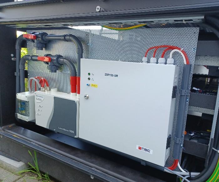
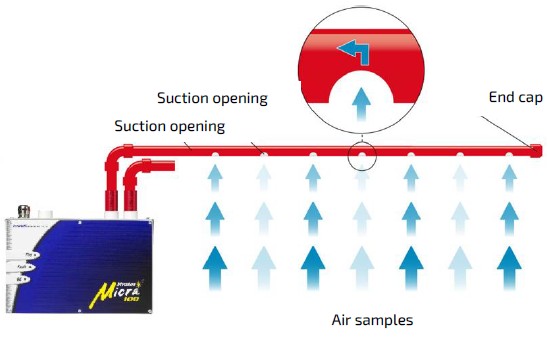
The Industrial L is optionally available with an independent fire alarm system. This is the STRATOS Micra 100 smoke aspiration system, featuring two separate aspiration lines with multiple sensing points. The system has its own UPS functionality to ensure it remains operational even in the event of a power outage. The fire detection system provides information on alarm and fault conditions. These conditions are transmitted to the FEMS and are thus displayed in Online Monitoring. |
|
Furthermore, the customer has the option of reading the status separately and thus connecting the fire detection system to an external monitoring station. To do this, the customer can define a signal in the range of 0 VDC to 24 VDC, which can be tapped via both NC and NO contacts. In addition, the system features both an audible and a visual alarm device on the electrical energy storage system itself, which is activated in the event of a fire.
Key Facts:
-
Aspiration smoke detector for early fire detection with a laser detection chamber
-
STRATOS Micra 100 with ClassiFire® adaptive artificial intelligence
-
Dust Suppression: Laser Dust Discrimination (LDD-3D3TM)
-
Certification in accordance with VdS/EN 54-20/LPCB/UL/FM
-
Distinguishes between smoke, dust, and exhaust fumes (Diesel)
-
No false alarms caused by operational disturbances
-
Automatic, continuous adjustment of the alarm threshold, resulting in optimal sensitivity
-
Sensitivity compensation in case of contamination
-
Monitoring of airflow, filter condition, and detector chamber
To be provided by the user — per system: (not included in the scope of delivery)
| Description | Specifications/Cross-Section | Quantity |
|---|---|---|
Feed-Through Terminal |
WAGO 2002-1301 |
16 |
End and Intermediate Plate |
WAGO 2002-1391 |
8 |
End Terminal |
WAGO 249-117 |
16 |
Connection cable |
UV-resistant/cable type, cross-section, and cable length must be evaluated on a case-by-case basis. |
1 |
Connection cable |
UV-resistant/cable type, cross-section, and cable length must be evaluated on a case-by-case basis (see electrical diagram). |
7 |
1.1. Connection to the optional fire detection system
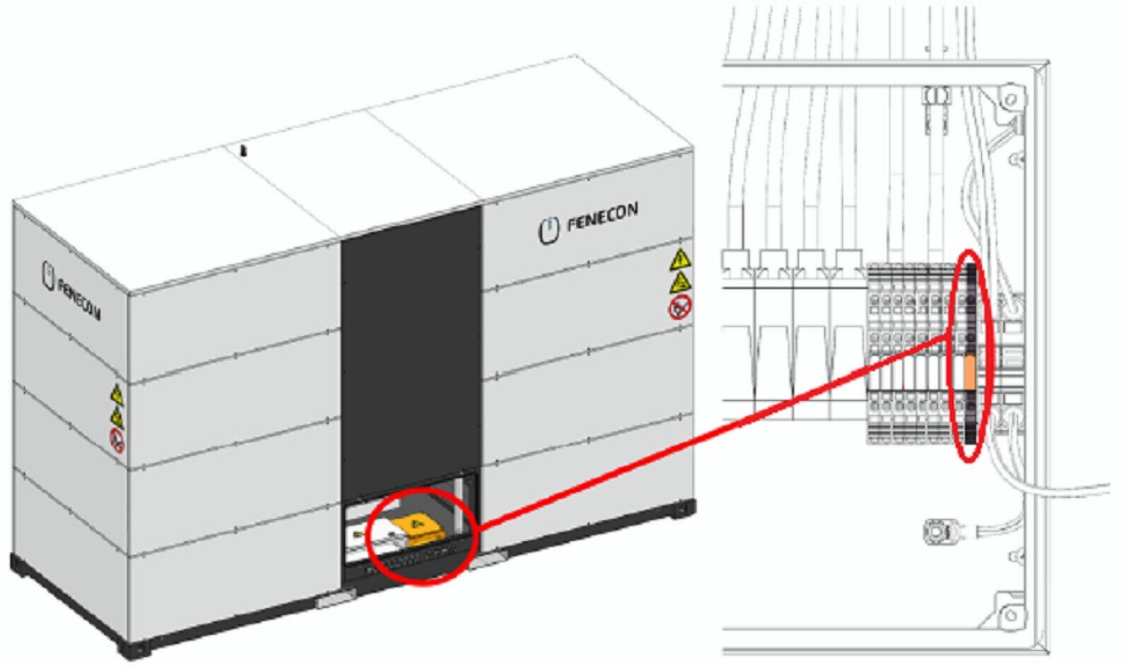
There are dry-contact terminals available that must be connected when the optional fire detection system is selected.
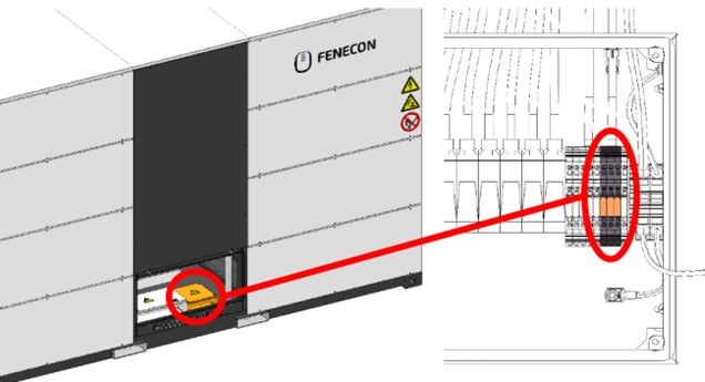
These can be found in the connection box on the back of the Industrial L:
For more information on this, see also the section titled 'Cable gland plate' and the electrical schematic.
| = ENERGY STORAGE SYSTEM + AKD - FA9 |
|---|
Terminal 1: INV1_enable- |
Terminal 1: INV1_enable+ |
2. Function and location of the fire detection system
Function of the fire detection system:
Location of the fire detection system:
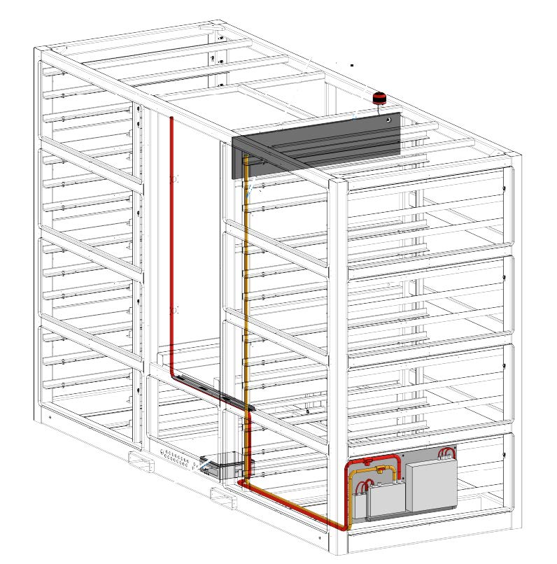
|
Location marked by an information sign (fire department): 
|
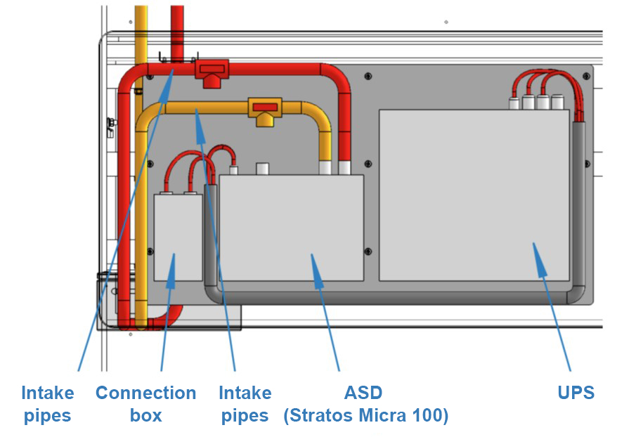
3. Connection to the external fire alarm system
The fire detection system can be connected to an external fire alarm control panel (FACP). This connection allows alarm and fault signals to be transmitted to an operator’s FACP. Potential-free contacts are available for connection to an external monitoring station:
-
1 x Trigger/alarm
-
1 x Fire alarm system malfunction These can be found in the connection box on the back of the Industrial L:
ENERGY STORAGE SYSTEM + AKD - FA6 |
|---|
Terminal 1 → Fire alarm system: Alarm relay NO |
Terminal 2 → Fire alarm system: Alarm relay NC |
ENERGY STORAGE SYSTEM + AKD - FA7 |
Terminal 1 → Fire alarm system: Relay C |
Terminal 2 → Fire alarm system: Relay Alarm C |
ENERGY STORAGE SYSTEM + AKD - FA8 |
Terminal 1 → Fire alarm system: Fault relay NO |
Terminal 2 → Fire alarm system: Fault relay NC |
For more information, see the sections titled [Junction box — Inverter] and [Terminal assignment — Communication connection box], as well as the E-Plan.
4. In the event of an alarm
|
To restart the system after a false alarm/fault, the fire detection system must be confirmed on site. |
|
A test alarm must only be tripped with real smoke. Use smoke sticks (item numbers ZUS1097 and ZUS1094) for this purpose. |
What happens when the fire detection system triggers:
-
The fire detection system interrupts the emergency stop circuit.
-
The DC battery contacts open.
-
An internal section switch in the inverter isolates the AC from the DC.
-
Fault report in Online Monitoring.
-
Flashing light: Acoustic and visual signal.
-
When connecting the customer’s own/external alarm system: The alarm signal is transmitted via a potential-free contact to the customer’s external FACP.
| Version/Revision | Change to the installation and service instructions | Date | Name |
|---|---|---|---|
V1_2024_02 |
Created |
02.2024 |
Veronika Moosreiner |
V2_2025_05 |
Cables and terminals between the battery and the inverter for the fire detection system shutdown |
05.2025 |
Veronika Moosreiner |