FENECON Industrial S — Assembly and Operating Instructions
1. About these instructions
These operating instructions are an integral part of the battery energy storage system and must be kept in its immediate vicinity and accessible to personnel at all times. Furthermore, all documents listed in the appendix to these operating instructions and the operating instructions of the component manufacturers must be observed.
Personnel must have carefully read and understood these operating instructions before starting any work.
1.1. Manufacturer
FENECON GmbH
Gewerbepark 6
94547 Iggensbach
Germany
Phone: +49 (0) 9903 6280 0
Fax: +49 (0) 9903 6280 909
E-mail: service@fenecon.de
Website: www.fenecon.de
1.2. Formal information on installation and service instructions
© FENECON GmbH, 2025
All rights reserved
Reprinting, even in part, is only permitted with the permission of FENECON GmbH.
1.3. Version/revision of the installation and service instructions
| Version/revision | Change to installation and service instructions | Date | Name |
|---|---|---|---|
V1 |
Initial version |
11/12/2023 |
FENECON GmbH |
V20240125 |
Supplement storage versions connection AA3 |
25/01/2024 |
FENECON GmbH |
2024.04.1 |
Revision/supplement to the instructions |
10/04/2024 |
FENECON GmbH |
2024.08.1 |
Revision of sections 3 & 6 |
12/08/2024 |
FENECON GmbH |
2025.03.1 |
Revision print version |
12/03/2025 |
FENECON MR |
1.4. Symbol conventions
|
||
|
||
|
||
|
||
|
1.5. Structure of warning notices
If observed, warnings protect against possible personal injury and damage to property. The signal word to classifies the magnitude of danger.
Warnings are structured according to the SAFE method:
| Signal word | Meaning |
|---|---|
S |
Signal word (DANGER, WARNING, CAUTION or NOTE) |
A |
Type and source of danger |
F |
Consequence |
E |
Escape |
|
Source of the danger
|
1.6. Terms and abbreviations
The following terms and abbreviations are used in the instructions:
| Term/Abbreviation | Meaning |
|---|---|
AC |
Alternating Current - alternating current |
ADR |
Accord européen relatif au transport international des marchandises dangereuses par route |
BMS |
Battery Management System |
DC |
Direct Current |
EMS |
Energy Management System |
FEMS |
FENECON Energy Management System |
ESS |
Energy Storage System |
HV |
High Voltage |
CX |
Commissioning |
GCP |
Grid Connection Point |
NMC |
Nickel-Manganese-Cobalt |
PE |
Protective Earth conductor |
PV |
Photovoltaics |
RCD |
Residual Current Device |
SoC |
State of Charge |
VDE |
German Association for Electrical, Electronic & Information Technologies e. V. |
Widget |
Component of Online Monitoring |
1.7. Appendix to this document
All documents listed in the appendix to these installation and service instructions must be observed.
See Applicable documents.
1.8. Availability
The operator must keep these installation and service instructions or relevant parts of them within easy reach in the immediate vicinity of the product.
If the product is handed over to another person, the operator passes these installation and service instructions on to that person.
2. Safety
2.1. Intended use
The FENECON Industrial S is a compact industrial energy storage system (power storage system) consisting of various modules. These include, in particular, efficient inverters, the FENECON Energy Management System (FEMS) and powerful batteries including thermal management. The energy storage system is used to store and supply electrical energy and is intended for connection to the 400 V/50 Hz public power grid.
The FENECON Industrial S series is available with an inverter output of 92 or 184 kVA and a capacity of 82 or 164 kWh.
The electrical energy storage system must only be used in compliance with the permissible technical data (see Technical data).
Any other use is not an intended use.
2.2. Field of application
The product is intended exclusively for use in the following areas of application:
-
Commercial use
|
The device is not intended for use in residential areas and cannot ensure adequate protection of radio reception in such environments. |
2.3. Qualification of staff
Qualified personnel must be deployed for the intended use, installation and maintenance of the system. The area of responsibility, competence and supervision of the personnel must be precisely regulated by the operator.
2.3.1. Qualified electricians
Qualified electricians include persons who:
-
are able to carry out work on electrical systems due to their technical training, experience and knowledge of the relevant standards and regulations.
-
have been commissioned and trained by the operator to carry out work on electrical systems and equipment of the battery system.
-
are familiar with how the battery system works.
-
recognize hazards and prevent them by taking appropriate protective measures.
-
have access to all maintenance information.
2.3.2. Specialist personnel (refrigerant technicians)
Specialist personnel include persons who:
-
are able to carry out work on the cooling system due to their technical training, experience and knowledge of the relevant standards and regulations.
-
have been commissioned and trained by the operator to carry out work on the cooling system.
-
are familiar with how the cooling system works.
-
recognize hazards and prevent them by taking appropriate protective measures.
-
have access to all maintenance information.
2.3.3. Service staff
Work that goes beyond connecting the system may only be carried out by the manufacturer’s specialist personnel. Other personnel are not authorized to carry out this work.
Service personnel includes manufacturer personnel or specialist personnel instructed and authorized by FENECON GmbH who must be requested by the operator to work on the Battery energy storage system (e.g. Assembly, repair, maintenance, work on the batteries, etc.).
2.4. Safety and protective devices
The safety devices must not be bypassed or switched off. Operating the electrical energy storage system without or with defective protective devices is prohibited. The safety devices must always be kept within easy reach and checked regularly.
2.4.1. Safety screws
All access points to the Battery energy storage system are locked with safety screws. Access is only possible with special tools. Only authorized specialists may open the housing.
|
The panel labeled "Control Cabinet" must only be opened for installation. All other system panels must only be opened when the system is unlocked and by personnel authorized by the manufacturer. |
2.4.2. HV battery emergency stop switch
In emergency situations, the batteries can be switched off using the emergency stop button. The emergency stop button must not be used to switch off the batteries normally. Battery energy storage is equipped with 1 emergency stop button.
The emergency stop switch is located inside the Battery energy storage unit.
If required by the operator, there is the option of installing an external emergency off switch, further information can be found in section Connection — Signal interface.
Pressing the emergency stop button
Pressing the emergency stop button triggers the following reaction:
-
The HV contactors in all batteries are switched off.
Once the emergency situation has been rectified, the emergency stop push-button must be unlocked before the system is switched back on.
Unlocking the emergency-off push-button
The emergency-off push-button must be unlocked before switching back on after a tripped emergency-off:
Acknowledge emergency stop
The emergency stop is acknowledged at the acknowledge button on the emergency stop switch.
There is also the option of installing an external acknowledgement key; further information can be found in the section Connection — Signal interface.
2.4.3. Earthing connections inside/outside
The electrical energy storage has 4 earthing connections, which are located at the bottom of the four corners. There is also a PE rail inside the Control Cabinet for the grid connection (see sections AC connection and Connection — Additional equipotential bonding).
2.5. Residual risks
|
The product is manufactured in accordance with the current state of the art and recognized safety principles, taking into account the relevant legal regulations. |
|
No access for unauthorized persons!
|
|
Risk of electric shock
|
|
Risk of burns
|
|
This signal word indicates actions to prevent damage to property. Observing these instructions prevents damage to or destruction of the system. |
2.6. Warnhinweise und Sicherheitshinweise
2.6.1. General information on the FENECON Industrial S Battery energy storage system
-
The batteries may only be removed or replaced by service personnel and transported using hazardous transportation.
-
The current laws, regulations and standards must be observed when transporting the battery energy storage system (e.g. Dangerous Goods Transportation Act (GGBefG, ADR).
-
The electrical energy storage system must only be used under the specified charging/discharging conditions (see section 3 Technical data).
-
Only use the Battery energy storage system as intended. Improper use can lead to overheating, explosion or fire of the battery modules.
-
Do not immerse the Battery energy storage system in water.
-
Keep away from water sources.
-
Prevent the ingress of water when working on the power storage system.
-
Switch off the damaged power storage system immediately and do not use it again.
-
Modifications to the electricity storage system are prohibited.
-
The electrical energy storage system must only be operated under the specified environmental conditions.
-
Do not use the power storage system if changes in color or mechanical damage are detected during Assembly, charging, normal operation and/or storage.
-
Eye and skin contact with leaked electrolyte solution must be avoided. After contact with eyes or skin, rinse/clean immediately with water and seek medical attention. Delayed treatment can cause serious damage to health.
-
Do not apply any mechanical force to the power storage system. The system can be damaged and short circuits can occur, which can lead to the system overheating, exploding or catching fire.
-
No soldering work may be carried out on the power storage system. Heat introduced during soldering can damage the system
-
The power storage system must not be dismantled or modified. Damage to the integrated safety mechanisms and protective devices can lead to overheating, explosion and/or fire in the power storage system.
-
An electricity storage system that exhibits odors and/or temperature increases, changes color and/or shape, leaks electrolyte solution or exhibits other anomalies must be shut down immediately, otherwise it may lead to overheating, explosion and/or fire.
-
Do not charge the batteries in an external charger.
-
Read the instructions for installation and operation to avoid damage due to incorrect installation/operation.
-
The battery modules may have insufficient cell voltage after a long storage period.
-
Do not expose the power storage system to high voltage.
-
Set up the electricity storage system on a level and load-bearing surface.
-
Do not place any objects on the power storage system.
-
The floor condition lies the responsibility of the operator.
2.6.2. Installation, operation and maintenance
Always observe the following safety instructions when installing, operating or maintaining the power storage system:
-
Installation/maintenance work on the battery storage system and making the cable connections may only be carried out by qualified personnel (qualified electricians).
-
During Assembly and maintenance work on the electricity storage system, stand on dry insulating objects and do not wear any metal objects (e.g. watches, rings and necklaces) during maintenance work/operation.
-
Use insulated tools and wear personal protective equipment.
-
The batteries can cause an electric shock and burns due to short-circuit currents.
-
Do not touch two charged contacts with a potential difference.
-
Measure the system voltage with a multimeter and ensure that the output voltage is 0 V when switched off.
-
If an anomaly is detected, switch off the energy storage system immediately.
-
Do not continue the maintenance work until the cause of the fault has been rectified.
2.6.3. Fire protection
-
The heat can melt insulation and damage the safety ventilation, which can lead to overheating, explosion or fire on the battery modules.
-
Do not heat the energy storage system.
-
Do not expose the energy storage system to naked flames.
-
Contact of the batteries with conductive objects (e.g. wires) is prohibited.
-
Do not set up or use the energy storage system near naked flames, heaters or high-temperature sources.
-
Keep the energy storage system away from sources of heat and fire, flammable, explosive and chemical materials.
-
Do not dispose of the battery modules in a fire due to the risk of explosion.
-
Do not store flammable materials in the container
-
Only use flame-retardant operating fluids and coolants
-
Clean extraction and ventilation systems regularly
-
Change dirty filter elements
2.7. Behavior in case of emergency
Proceed as follows in emergency situations:
-
Disconnect the electricity storage system from the grid
-
Leave the zone of danger immediately
-
Secure the zone of danger
-
Inform those responsible
-
Alert a doctor if necessary
2.8. Reasonably foreseeable misuse
All applications that do not fall within the scope of the intended use are considered misuse.
Work on live parts is generally not permitted. Electrical work may only be carried out by qualified electricians.
The following safety rules must be observed for all work on electrical components:
-
Disconnect.
-
Secure against restarting.
-
Check that there is no voltage.
-
Earth and short-circuit.
-
Cover or shield neighboring and live parts.
-
Non-compliance with the safety rules is considered a reasonably foreseeable misuse.
- Other misuses include in particular
-
The product may be damaged by improper transportation, installation, assembly or trial operation.
-
Change in the specified technical characteristics, including the individual components.
-
Change or deviation of the connected load.
-
Functional or structural changes.
-
Operating the product in a faulty or defective condition.
-
Improper repairs.
-
Use by untrained persons (instruction in accordance with the installation and service instructions is provided by the operator).
-
Operation without protective devices or defective protective devices.
-
Disregarding the information in the original installation and service instructions.
-
Unauthorized or unauthorized access via the control unit or the network.
-
Fire, open flames and smoking in the vicinity of the storage system.
-
Insufficient ventilation.
-
Unauthorized changes and actions to the electrical energy storage system.
-
Private use.
-
Use as mobile energy storage.
-
Direct use in a PV system (only one AC-side grid feed-in possible).
-
2.9. Pictograms
Pictograms on the system indicate dangers, prohibitions and instructions. Illegible or missing pictograms must be replaced by new ones.
| Piktogramm | Bedeutung | Position |
|---|---|---|

|
Warnung vor gefährlicher elektrischer Spannung |
Piktogramm am Gehäuse, und Kennzeichnung von Komponenten, bei denen nicht klar zu erkennen ist, dass sie elektrische Betriebsmittel enthalten, die Anlass für ein Risiko durch elektrischen Schlag sein können. |

|
Vor Benutzung erden |
Im Bereich der Erdungsanschlüsse (z. B am Container). |

|
Warnung vor heißer Oberfläche. |
|

|
Allgemeines Warnzeichen. |
|

|
Warnung vor Gefahren durch das Aufladen von Batterien |
Piktogramm am Gehäuse und Kennzeichnung von Komponenten, bei denen nicht klar zu erkennen ist, dass sie elektrische Betriebsmittel enthalten, die Anlass für ein Risiko durch das Aufladen von Batterien sein können. |

|
Allgemeines Verbotszeichen. |
|

|
Keine offene Flamme; Feuer, offene Zündquelle und Rauchen verboten |
Piktogramm am Gehäuse und Kennzeichnung von Komponenten, bei denen nicht klar zu erkennen ist, dass sie elektrische Betriebsmittel enthalten, die Anlass für ein Risiko durch offene Flammen, Feuer, offene Zündquellen und Rauchen sein können. |

|
Getrennte Sammlung von Elektro- und Elektronikgeräten |
An den Batterien. |

|
Anleitung beachten. |
|

|
Kopfschutz benutzen. |
|

|
Fußschutz benutzen. |
|

|
Handschutz benutzen. |
2.10. Operating materials/equipment
2.10.1. Electrolyte solution of the battery modules
-
Electrolyte solution is used in the battery modules (NMC).
-
The electrolyte solution in the battery modules is a clear liquid and has a characteristic odor of organic solvents.
-
The electrolyte solution is flammable.
-
The electrolyte solution in the battery modules is corrosive.
-
Contact with electrolyte solution can cause severe burns to the skin and damage to the eyes.
-
Do not inhale the vapors.
-
If the electrolyte solution is swallowed, induce vomiting.
-
Leave the contaminated area immediately after inhaling the vapors.
-
After contact with skin, wash thoroughly with soap and water.
-
After contact with eyes, rinse with running water for 15 minutes as soon as possible; consult a doctor immediately.
|
Further information on the electrolyte solution can be found in the manufacturer’s safety data sheet. |
2.10.2. Refrigerant of the cooling system
-
Contains pressurized gas, may explode when heated.
-
Protect from sunlight and store in a well-ventilated place.
-
Rapid evaporation of the liquid can cause frostbite.
-
Misuse or intentional inhalation can be fatal without alarming symptoms due to effects on the heart.
-
May cause cardiac arrhythmia.
|
The refrigerant used in the integrated air conditioning system is R134a. |
2.10.3. Electrical equipment
-
Work on electrical equipment may only be carried out by qualified electricians.
-
Maintenance work may only be carried out by trained specialist personnel (service personnel).
-
Before starting work on the electrical energy storage system, visually check for insulation and housing damage.
-
Regular checks for insulation and housing damage must be carried out.
-
The system must never be operated with faulty or non-operational electrical connections.
-
To avoid damage, lay supply lines without crushing and shearing points.
-
Only insulated tools may be used for maintenance on uninsulated conductors and terminals.
-
The entire energy storage system and its individual components (e.g. Inverter housing) must always be kept locked. Only authorized personnel with appropriate training and safety instructions (e.g. service personnel) should be allowed access.
-
Observe the inspection and maintenance intervals for electrical components specified by the manufacturer.
-
To avoid damage, lay supply lines without crushing and shearing points.
-
If the power supply is disconnected, specially marked external circuits may still be live!
-
Dangerous residual voltages may still be present on some equipment (e. g. inverters) with an electrical DC link for a certain period of time after disconnection.
| Before starting work on these systems, check that they are de-energized. |
2.11. Notes on occupational health and safety
The obligations arising from occupational health and safety must be implemented by the operator of the low-voltage equipment.
The obligations include the following points.
-
Provision of these operating instructions or extracts thereof to persons who carry out tasks in connection with the product.
-
Instruction of persons with regard to the intended use as well as the prohibited use.
-
Instruction of persons with regard to protective equipment and supplementary protective equipment.
-
Instruction of persons with regard to all residual risks.
2.12. Personal protective equipment
Depending on the work on the system, personal protective equipment must be worn:
-
Protective footwear
-
Protective gloves, cut-resistant if necessary
-
Protective eyewear
-
Protective headgear
2.13. Spare and wear parts
The use of spare and wear parts from third-party manufacturers can lead to risks. Only original parts or spare and wear parts approved by the manufacturer may be used. The instructions for spare parts must be observed.
|
Request further information from the manufacturer. |
2.14. IT Security
FENECON energy storage systems and their applications communicate and operate without internet connection. The individual system components (inverters, batteries, etc.) are not directly connected to the internet or accessible from the internet. Sensitive communications via the internet are processed exclusively via certificate-based TLS encryption.
Access to the programming levels is not barrier-free and is accessible at different levels depending on the qualifications of the operating personnel. Safety-relevant program changes require additional verification.
FENECON processes energy data of European customers exclusively on servers in Germany and these are subject to the data protection regulations applicable in this country.
The software used is checked using automated tools and processes established during development in order to keep it up to date and to rectify security-relevant vulnerabilities at short notice. Updates for FEMS are provided free of charge for life.
3. Technical data
3.1. General information
| Product variant | ISK010 | ISK011 | ISK110 |
|---|---|---|---|
Number of Inverters |
1 |
2 |
|
Inverter power in kVA (total) 1 |
92 |
184 |
|
Number of batteries |
2 |
4 |
|
Nominal battery capacity in kWh (total) |
84.5 |
169.0 |
|
Usable battery capacity in kWh (total) 2 |
82 |
164 |
|
Max. Continuous phase current in A |
152 |
285 |
|
Rated AC voltage in V |
400/230V, 3P + N + PE |
||
Rated frequency in Hz |
50 |
||
Battery technology |
Nickel Manganese Cobalt (NMC) |
||
Cooling medium battery |
R134a |
||
Cooling medium Inverter and climate control unit |
Air |
||
Internal lighting (operation) |
Min. 300 lux |
||
Expected time-averaged measurement surface sound pressure level at a distance of 1 m (according to DIN EN ISO 3744: 2011-02) 3 |
65 dB(A) |
||
Installation location |
Outdoor |
||
1 Nominal power at nominal conditions; the actual power depends on other factors such as state of charge, ambient temperature and cell temperatures.
2 DC-side at 25 °C and 0.2 C (see guarantee conditions at docs.fenecon.de)
3 The actual noise exposure caused by the product depends on the ambient conditions. Therefore, the operator must carry out further noise measurements at the installation site of the product in accordance with the BimSchG.
3.2. Ambient conditions
The following ambient conditions must be observed during operation and storage.
| Description | Value/dimension |
|---|---|
Operating or storage altitude above sea level |
≤ 2000 m |
Ambient temperature (operation/storage) |
-20 °C … +40 °C |
Relative humidity (operation/storage) |
50 % non-condensing (up to 90 % permissible for short periods) |
|
The container is not suitable for installation in a marine environment. |
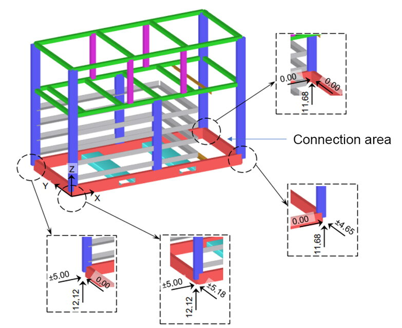
3.3. Dimensions


The centers of gravity of the Industrial S variants are within the tolerance specified in Image: Electrical energy storage with dimensions and Image: Transport dimensions, electrical energy storage with transport rails.
Additional transport rails are required to transport the system, which increases the external dimensions (see image and section Transport).
| Product variant | ISK010 | ISK011 | ISK110 |
|---|---|---|---|
External dimensions in mm L x W x H |
2640 x 1210 x 1875 |
||
External dimensions in mm L x W x H incl. transport rail |
2640 x 1420 x 1875 |
||
3.4. Weights
| ISK010 | ISK011 | ISK110 | |
|---|---|---|---|
Net weight in kg |
1710 |
2260 |
2340 |
Gross weight in kg (transport weight) |
1770 |
2320 |
2400 |
3.5. Type label
The type label is located on the outside of the electrical energy storage unit and also on the inside of the Control Cabinet.
The image type label shows an example of the core information of the electrical energy storage device and its serial number.

The serial number is made up of the following information:
-
Product variant (see section 3 Technical data, General, e. g. ISK110)
-
Revision status (see section Version/revision of the electrical energy storage system at the beginning of this document, e. g. AA2)
-
Unique number

3.5.1. Battery energy storage version/revision
The revision number of the Battery energy storage system reflects the hardware structure. If differences occur in the course of modifications, this is indicated and described in these operating instructions by means of a revision number. If no explicit revision number is specified, the description applies to all revision levels.
4. General description
The FENECON Industrial S is a compact industrial electrical energy storage system consisting of various modules. These include, in particular, efficient inverters, the FENECON Energy Management System (FEMS) and a powerful automotive full pack including thermal management.
The FENECON Industrial S electrical energy storage system is available with an inverter output of 92 or 184 kVA and a capacity of 82 or 164 kWh.
The FENECON Industrial S is an electrical energy storage system for outdoor installation.

4.1. System structure
The inverters and the climate control unit are located in the upper part of the system. The all-round cladding grilles protect the components against direct weathering and contact. In addition, the surrounding grilles allow ideal ventilation of the components for cooling. The grilles must not be covered and the minimum distances from the section [Selecting and preparing the installation site] must be observed.
The batteries and electrical components are located in the lower part of the system. This area is watertight to the outside.
4.1.1. Overview — System components

| Position | Component | Comment |
|---|---|---|
1 |
LTE antenna |
|
2 |
Climate control unit |
|
3 |
Control Cabinet |
|
4 |
Low-voltage distribution |
|
5 |
Control components |
|
6 |
Inverter 2 (only for ISK110) |
ISK011 PAR box, ISK010 unequipped |
7 |
Inverter 1 |
|
8 |
Switch cabinet lighting with 230 V socket for service laptop |
|
9 |
Emergency-off for HV batteries |
|
10 |
Acknowledgement key for emergency-off |
|
11 |
RJ45 port for service |
|
12 |
Cable entry at the front |
Alternative: From below the system |

| Position | Components | Comment |
|---|---|---|
1 |
Controller — Climate control unit |
|
2 |
Automotive batteries incl. BMS |
|
3 |
HV-800 box |
|
4 |
Climate control unit |
|
5 |
F2B |
|
6 |
Refrigerant distributor |
4.1.2. Components — Control Cabinet
The control cabinet describes the control cabinet of the power storage system and contains the low-voltage distribution and the control components. This component is located behind the facing tile labeled "Control Cabinet".
|
Different versions are shown below depending on the revision status. (see Version/revision of the electrical energy storage system at the beginning of this document) |
Control Cabinet (AA1, AA2)

| Position | Description | Comment |
|---|---|---|
1 |
Fuse auxiliary consumer |
-F3 |
2 |
Fuse inverter 1 |
-F1 |
3 |
Fuse inverter 2 |
-F2/only equipped with ISK110 |
4 |
Connection terminals 3-phase rail system |
-X1/Customer connection |
5 |
N-rail |
-/Customer connection |
6 |
PE rail |
-/Customer connection |
7 |
C-rail for cable clamps |
-/- |
8 |
Supply line overvoltage protection |
-U1/phase L1 |
9 |
Communication incl. overvoltage protection |
-F11, -F12, -F13, -F14, -F21, -F22, -F23/Customer connection |
10 |
Power supply unit (24 V) |
-T1 /- |
11 |
Buffer module (24 V) |
-T2 /- |
12 |
FEMS |
-K1 /- |
13 |
LTE router |
-K4 /- |
14 |
Emergency-off relay |
-U5 /- |
15 |
Relay air conditioning unit |
-Q4 /- |
16 |
Relay acknowledgement key |
-Q5 /- |
17 |
Switch |
-A7 /- |
18 |
Fuses (24 V) |
-K50 /- |
19 |
Fan |
-EC1 /- |
20 |
Thermostat |
-EC2 /- |
21 |
Fuse consumer load Control Cabinet |
-F6/MCB switch 24 V power supply unit |
22 |
Fuse for air conditioning unit |
-F4/RCD |
Control Cabinet (AA3, AA4)

| Position | Description | Comment |
|---|---|---|
1 |
Fuse auxiliary consumer |
-F1/- |
2 |
Fuse inverter 1 |
-F2/- |
3 |
Fuse inverter 2 |
-F3/only equipped with ISK110 |
4 |
Connection terminals 3-phase rail system |
-X1/Customer connection |
5 |
N-rail |
customer connection |
6 |
PE rail |
Customer connection |
7 |
C-rail for cable clamps |
-/- |
8 |
Supply line overvoltage protection |
-F9/Phase L1 |
9 |
Communication incl. overvoltage protection |
-X13, -F18, -F19/Customer connection |
10 |
Power supply unit (24 V) |
-T1/- |
11 |
Buffer module (24 V) |
-C1/- |
12 |
Fuses (24 V) |
-K50/- |
13 |
Switch |
-K8/- |
14 |
LTE router |
-K6/- |
15 |
Emergency-off relay air conditioning unit |
-K5/- |
16 |
Relay air conditioning unit |
-K2/- |
17 |
Relay acknowledgement key |
-K3/- |
18 |
FEMS |
-K1/- |
19 |
Fan |
-EC2/- |
20 |
Thermostat |
-EC1/- |
21 |
Fuse consumer load Control Cabinet |
-F6/MCB-switch 24 V power supply unit |
22 |
Fuse for air conditioning unit |
-F5/RCD |
4.2. Inverter
Up to two inverters (KACO gridsave 92.0 kVA) are installed in the system to transfer power between the battery and the grid or vice versa.
Inverter guidelines:
VDE AR-N 4105 2018-11; VDE AR-N 4110/4120:2018-11,
TOR generator type A:2019-12/TOR generator-A+R25/TOR generator-B
|
Further information on the inverters is contained in the manufacturer’s documentation and is valid for this product (see Applicable documents). |
4.3. Low-voltage distribution
The low-voltage distribution is the power transfer point to the operating system.
|
Further information can be found in the AC grid connection section. |
4.4. Control components
The control cabinet serves as the central control unit for the electrical energy storage system. The control cabinet contains the communication connection and the interface for connecting the operator.
The following components are located on a remote panel in front of the control components:
-
Service Port
-
Emergency stop for HV batteries
-
Acknowledgement key
The air conditioning control system is located in a remote control cabinet in the upper area.
|
Further information can be found in the sections Connection — Communication and Connection — Signal Interface. |
4.5. Air conditioning unit
The air conditioning system is an air-cooled compressor cooling system and is specially designed for the system.
Further information on the integrated air conditioning system can be found in the manufacturer’s documentation.
|
Use the miniature circuit breaker (MCB) described in the Components — Control Cabinet section to disconnect the climate control unit from mains. |
|
Further information on the integrated air conditioning unit can be found in the manufacturer’s documentation (see Applicable documents). |
4.6. FEMS — FENECON Energy Management System
|
Information on FENECON Energy Management System can be found on the website https://docs.fenecon.de/. |
5. Scope of delivery
The Battery energy storage container is delivered fully pre-wired. The container contains the batteries, the inverters, the air conditioning unit and the control components. The accessory box is also included. Furthermore, the two profiles for securing the load and for crane transportation are on the container when it is delivered.
| Item | Component | Amount | Comment |
|---|---|---|---|
1 |
Cabled container including climate control unit, inverter, control cabinet and batteries |
1 |
|
2 |
Container cover |
1 |
Return to FENECON |
3 |
Industrial S accessory box |
1 |
|
3.1 |
Operating instructions |
1 |
|
3.2 |
Meters for grid connection |
1 |
|
3.3 |
Busbar terminal: SK 300 F10, 608 A, 30 Nm, 120-300 mm2 |
2 |
|
3.4 |
Busbar terminal: SK 185 F10, 448 A, 24 Nm, 35-185 mm2 |
2 |
|
3.5 |
Bracket clamp (16-22 mm), single metal pressure trough, FT → 120 mm2 with counter trough |
5 |
|
3.6 |
Bracket clamp (28 mm), single metal pressure tray, FT → > 120 & < 300 mm2 with counter tray |
5 |
|
3.7 |
Bracket clamp (24-28 mm), single metal pressure tray, FT → 300 mm2 with counter tray |
5 |
|
3.8 |
5-star bit — Safety bit |
4 |
1 piece, enclosed with delivery bill |
3.9 |
5-star replacement screws |
5 |
The equipment of the container depends on the variant of the FENECON system ordered.
The Self-Consumption Optimization application is included in the scope of delivery as standard. Further software licenses for operating the system are not included in the standard scope of delivery. Furthermore, the read and write access or Peak Shaving applications can be purchased optionally; these can be installed both retrospectively and directly during commissioning. The instructions for FEMS applications for the electrical energy storage system can be found on the FENECON website in the download center: https://docs.fenecon.de/
6. Assembly and assembly preparation
The Battery energy storage system is delivered ready for connection and still needs to be set up and connected at the installation site.
Before installation, carefully check whether the product is damaged and whether all accessories listed in the scope of delivery are included. If a part is missing or damaged, contact the manufacturer/dealer.
Residual risks:
|
Incorrect operation
|
|
Incorrect operation can lead to material damage.
|
6.1. Warnhinweise und Sicherheitshinweise
|
Risk of electric shock
|
|
Electric shock from live parts
|
|
Electric shock in the absence of overvoltage protection
|
|
Fire and explosion
|
|
Fire and explosion with deeply discharged battery modules
|
|
Toxic substances, gases and dusts
|
|
Destruction of a measuring device due to overvoltage
|
|
Hot surfaces
|
|
Sand, dust and moisture
|
|
Electrostatic charging
|
|
Cleaning agents
|
|
Installation site
|
|
Installation
|
6.2. Tools/machines required
The following tools and machines are required for assembly of the Battery energy storage system:
| Description | Comment |
|---|---|
Forklift truck |
Minimum load capacity must be selected in accordance with table Technical data — Weights. |
Crane |
Alternative to forklift truck; minimum load capacity must be selected according to table Technical data — Weights. |
Multimeter |
|
Socket wrench set/ratchet box |
|
Hexagon socket wrench set |
|
Qualified electrician’s toolbox |
|
5-star bit — Safety bit |
1 piece enclosed with the delivery bill |
6.3. Assembly sequence
The electrical energy storage system is delivered with the transport crossbars fitted and covered with a cover.
Before assembly, a suitable installation site must be prepared in accordance with section Select and prepare the installation site; if necessary, the Cable entry variant must also be taken into account here.
A forklift or crane can be used to unload the container from the truck; the information in the Transport section must be observed.
Once the energy storage system has been positioned at the place of intended use in accordance with all the instructions in this manual, proceed as follows:
-
Dismantle transport traverses/transport rails (see Disassembly — Transport rail).

| Item | Name | ERP number | Torque | Quantity |
|---|---|---|---|---|
1 |
Hexagon head bolt, fully threaded M20 * 50 |
ZUS902 |
60 Nm |
4 |
2 |
Disc with large outside diameter D22.0 |
ZUS903 |
4 |
|
3 |
Flat gasket d20DN15 |
ZUI1191 |
4 |
|
4 |
Transport fuse |
ZUI993 |
2 |
-
Remove the cover (return to FENECON).
-
Reinstall the previously removed bolts of the transport crossbar, the bolt assembly and the torque can be found in the image Disassembly — transport rail.
-
To connect the electrical energy storage, open the facing tile labeled "Control Cabinet" (see image Disassembly/assembly of the control cabinet — Facing tile).
|
The facing tile labeled "Control Cabinet" must only be opened for installation. All other system panels must only be opened when the system is unlocked and by personnel authorized by the manufacturer. |
|
A safety bit is required to remove the facing tile; this is included with the delivery bill and in the accessories box. |
|
Inside the electrical energy storage unit is the accessory box containing the material required to connect the system. |

| Pos | Name | ERP number | Tightening torque | Quantity |
|---|---|---|---|---|
1 |
Control Cabinet panel |
1 |
||
2 |
Safety bolt M6 x 16 |
ZUI739 |
6 Nm |
8 |
3 |
Disc polyamide 6.6 natural D6.4 |
ZUI816 |
8 |
-
Connect the electrical energy storage system in accordance with section Electrical installation.
-
After completing the assembly work, the electrical energy storage unit must be properly closed again. The screw assembly and the required torque can be found in the image Disassembly/Assembly Control Cabinet — Facing tile.
|
Dirt, rain or snow must be prevented from entering the open electrical energy storage system during installation work. |
6.4. Select and prepare the installation site
6.4.1. General information
The operator of the system is responsible for selecting and preparing a suitable installation site for the energy storage system. In addition, the permissible environmental conditions must be complied with and the area of use must be observed.
If contact with vehicles (e. g. near a parking lot or road) is conceivable/possible, the system must be protected.
The earthing system must be designed in accordance with the locally applicable requirements. (see section Connection — Additional equipotential bonding).
|
Installation site
|
|
The installation site must be well lit. |
6.4.2. Space requirement at the installation site
The container is designed in such a way that the battery storage system must be accessible from all sides during installation and for maintenance purposes.
Permanently maintain a minimum distance (green) (cf. Installation concept — Space requirements) of 1.2 m around the entire system for ventilation and for maintenance and service work.
The distances to be maintained are shown in the image. The arrow represents the airflow direction of the inverters and the climate control unit.

The maneuvering path required for a forklift or crane to set up the electrical energy storage system is not taken into account in the installation concept. This must be planned independently by the operator.
In addition, an additional maneuvering path (blue) of at least 4 m must be provided for a forklift truck on the opposite side of the Control Cabinet in the event of a battery replacement.
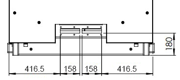
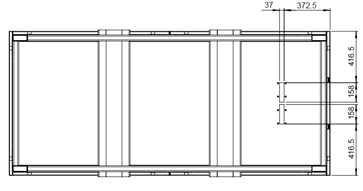
6.4.3. Substrate/foundation
The electrical energy storage system must be positioned on a sufficiently stable surface at the installation site to ensure that it stands securely. This can be, for example, a point foundation consisting of 4 points, a strip foundation or a slab foundation. Information on the dimensions of the foundation can be determined using the load transfer points of the electrical energy storage system (see image). The cable entries must be taken into account when preparing the foundation (see section Cable entry).
|
If necessary, the foundation must be designed to prevent slippage and movement. |
|
There should also be an air gap between the base and housing to prevent corrosion. |
6.5. Cable entry
The cables can be inserted either from below or from the side. (see image cable entry from the front, image cable entry from below) By default, the cable entry is mounted at the front. Modification may be necessary. A cover plate is already fitted to seal the unused entry.
Further information on the assembly of Roxtec cable feed-throughs can be found in the manufacturer’s data sheets (see Applicable documents).

| Amount of cable | Cable diameter in mm | Function |
|---|---|---|
5 |
9.5-32.5 |
AC connection 3 P, N, PE |
6 |
3.6-16.5 |
6 x communication |
The positions of the cable entry from below and from the front are shown below. For cable entry from the front, the operator is responsible for installing the cables in such a way that there is no risk of tripping for passers-by.
The necessary normative bending radius must be observed when inserting the cable.
6.6. Electrical installation
6.6.1. System integration
The image Standard structure of the system shows the structure of a standard customer network with an Industrial S.
The integration of an AC generator is also shown as an example; this is highlighted in blue. The associated inverter and the additional meter are not included in the scope of delivery of the Industrial S. This system structure can be an example for the application of self-consumption optimization.

| No. | Designation | Comment |
|---|---|---|
1 |
Grid connection meter |
|
2 |
Current transformer at NAP |
|
3 |
Voltage tap at the NAP |
|
4 |
Current meter at the NAP |
|
5 |
RS485 bus |
|
6 |
Current meter at the generator |
Example additional AC generator |
7 |
Current transformer at the generator |
Example additional AC generator |
8 |
Voltage tap at the generator |
Example additional AC generator |
9 |
PV Inverter |
Example additional AC generator |
10 |
RCD type A |
|
11 |
Fuse and mains circuit breaker |
|
12 |
Grid connection Battery energy storage |
|
13 |
Industrial S |
|
14 |
Consumption |
6.6.2. AC grid connection
The system has a low-voltage distribution system that supplies both the inverters and the auxiliary consumers. The electrical connection data can be found in the table AC grid connection.
The grid connection to the low-voltage distribution is made using terminal points (see image AC connection). The cable cross-sections must be selected in accordance with the local installation regulations. The terminal range that can be connected to the electrical energy storage can be found in the table Cable cross-section — AC connection. Table Connection areas — Strain relief — AC connection lists the strain reliefs to be installed; these are included in the accessories box. The corresponding counter tray must also be used during assembly.
The operator is responsible for installing a mains disconnection device for the electrical energy storage system in the supply line, which can be secured against being switched back on.
In addition, an RCD type A with a rated residual current of 3 A must be installed in the supply line of the electrical energy storage system.
|
Electric shock due to missing mains isolating device
|
|
Electric shock due to missing residual current device (RCD)
|
| ISK010 | ISK011 | ISK110 | |
|---|---|---|---|
Fuse |
Gg 200 A |
Gg 350 A |
|
Max. Continuous phase current in A |
152 |
285 |
|
Rated AC voltage in V 3.1+^. |
400/230, 3P + N + PE |
Rated frequency in Hz 3.1+^. |
50 |
Grid shape |
TN, TT |
||

| Conductor | Terminal | Cross-section1 | Torque | Outer diameter of conductor2 |
|---|---|---|---|---|
L1, L2, L3 |
Wöhner |
95 … 300 mm2 |
24 … 36 Nm |
16 … 32 mm |
N, PE |
Pollmann |
16 … 120 mm2 |
24 Nm |
16 … 32 mm |
Pollmann |
120 … 300 mm2 |
30 Nm |
1Applies only to multi-wire, directly clamped round copper conductors. Different materials and designs permitted in accordance with the terminal manufacturer’s specifications.
2Depending on the outer diameter, the appropriate strain relief clamp must be used in accordance with the Connection area table.
| Outer diameter of cable | Max. Tightening torque |
|---|---|
16 … 22 mm |
3.0 Nm |
22 … 28 mm |
3.0 Nm |
28 … 32 mm |
5.0 Nm |
6.6.3. Connection — Additional equipotential bonding
If the local installation regulations require an additional potential equalization in addition to the PE connection, this can be established via the housing. For this purpose, the Storage unit has connections with M10 threads at the bottom of all four external corners. The earthing system must be designed in accordance with the locally applicable requirements.
The earthing lugs can be connected directly to the marked points of the earthing connections on the container using screw connectors (see image rear earthing connection and image front earthing connection).
|
The Storage unit must be integrated into the on-site lightning protection concept. |


6.6.4. Connection — Communication
|
For commissioning, service and online monitoring, the operator must provide the Battery energy storage system with a permanent Internet connection to ensure proper operation. |
|
Different versions are shown below depending on the revision status (see [Version/revision of the electrical energy storage system]). |
Connection — Communication (AA1, AA2)
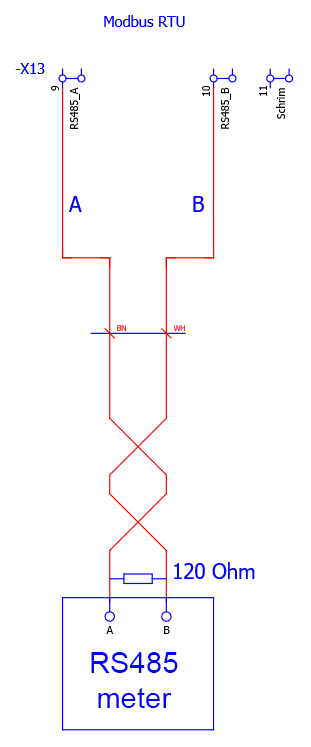
The image shows the junction box for communication and signals. The electrical energy storage has two Ethernet interfaces and one RS485 interface (see Table). This is followed by connection example for the RS485 interface.
During assembly, the cables must be attached to the plastic holder below using cable ties for strain relief.

| BMK | Interface | Specification | Connection | Outer diameter and specification of the cable |
|---|---|---|---|---|
F21 |
Modbus RTU |
|
Terminal |
4 … 16 mm |
F22 |
Modbus-TCP API |
Ethernet |
RJ45 socket |
4 … 16 mm |
F23 |
Internet1 |
Ethernet |
RJ45 socket |
4 … 16 mm |
1Not necessary when using the LTE router built into the Storage unit.
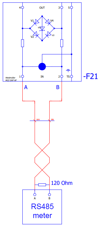
Connection — Communication (AA3, AA4)
The image shows the junction box for communication and signals. The electrical energy storage has two Ethernet interfaces and one RS485 interface (see Table). This is followed by connection example for the RS485 interface.
During assembly, the cables must be attached to the underlying plastic holder for strain relief using cable ties.

| BMK | Interface | Specification | Connection | Outer diameter and specification of the cable |
|---|---|---|---|---|
-F18 |
Modbus-TCP API |
Ethernet |
RJ45 socket |
4 … 16 mm |
-F19 |
Internet1 |
Ethernet |
RJ45 socket |
4 … 16 mm |
-X13.9 |
Modbus RTU A |
|
Terminal |
4 … 16 mm |
-X13.10 |
Modbus RTU B |
1Not necessary when using the LTE router built into the Storage unit.
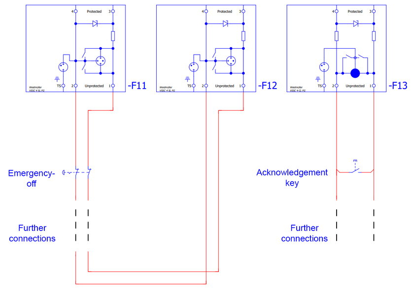
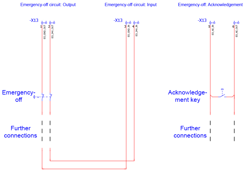
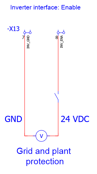
6.6.5. Connection — Signal interface
In addition to the communication interfaces, the electrical energy storage system also has the option of integrating one or more external emergency-off switches for the batteries and acknowledgement keys. It is also possible to control the coupling switches integrated in the inverter, e. g. for grid and plant protection in the customer’s system.
|
Different versions are shown below depending on the revision status (see section [Version/revision of the electrical energy storage system]). |
Connection — Signal interface (AA1, AA2)
The junction box is shown in the image.
Signal cables with the following specifications can be connected:
-
Outer diameter: 4 … 16 mm
-
Cross-section: 0.5 … 4 mm2
-
Cables with shielding are mandatory.
The connection of an external emergency stop command device is shown as an example in the following image:
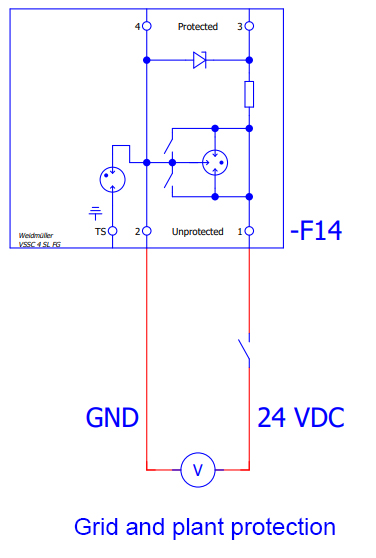
The inverters used have an internal coupling switch that can be used e. g. for external grid and plant protection. A connection example can be found in the corresponding drawing.
Connection — Signal interface (AA3, AA4)
The junction box is shown graphically in the image.
Signal cables with the following specifications can be connected:
-
Outer diameter: 4 … 16 mm
-
Cross-section: 0.25 … 4 mm2
-
Cables with shielding are mandatory.
The connection of an external emergency stop command device is shown as an example in image.
The inverters used have an internal section switch that can be used e. g. for external grid and plant protection. A connection example can be found in the corresponding drawing.
6.6.6. Connection — Grid meter
There are separate installation and configuration instructions for the 3-phase sensor, which contain the technical data and connection overview. These instructions can be downloaded from the FENECON website at:
https://docs.fenecon.de/de/fems/fems-app/installationsanleitungen/KDK_2PU_CT_Installationsanleitung.html
can be downloaded. The connection to the RS485 interface is described in the section Connection — Communication.
The meter included in the scope of delivery is for the grid connection point. It is a KDK 2PU CT measuring transformer meter. The transformers are not included in the scope of delivery.
Please note
The secondary current of the transformer must be 1 A or 5 A.
The meter supplied is intended for the grid connection point. However, in order to display production correctly in Online Monitoring, all generators must also be measured. This is the only way to ensure that the actual consumption can be calculated correctly. Certain PV inverters can communicate directly with the FEMS hardware and therefore do not require a separate meter for generation measurement; these inverters can be found on the FENECON website at link:https://fenecon.de/fenecon-fems/fems-app-pv-wechselrichter/.
7. Initial commissioning
7.1. Commissioning through service support
Residual risks:
|
Incorrect operation
|
|
Incorrect operation can lead to material damage.
|
Commissioning is carried out with the support of our service team. Please arrange an appointment for remote commissioning in advance with your contact person at FENECON.
For support, please contact:
FENECON GmbH
Gewerbepark 6
94547 Iggensbach
GERMANY
+49 (0) 9903 6280 0
service@fenecon.de
During commissioning by the service support, a commissioning report must be completed and signed jointly by the electrician and the end customer. It must then be sent to FENECON by e-mail, fax or post within 30 days of installation.
This IBN protocol is a prerequisite for the validity of the warranty. No warranty claims can be made without this protocol.
7.2. Requirements for commissioning
7.2.1. Checking the installation, connections and cabling
Check the system as follows before initial commissioning:
-
All components (distances, environment, mounting) are installed correctly.
-
All internal wiring is complete and properly connected.
-
All external supply lines (power supply, communication cable) are properly connected.
-
All connected loads are matched to the system and the necessary settings have been made.
-
All necessary tests of the energy storage system were carried out in accordance with standards.
7.2.2. Internet connection
First, establish a permanent internet connection to ensure access to FEMS Online Monitoring. This is basically ensured by two different options. By connecting with a LAN cable or with an LTE router (see section Connection — Communication).
8. FEMS — FENECON Energy Management System
8.1. Technical documentation — FEMS
The technical documentation of FEMS must be observed; this can also be found on the FENECON website at: www.docs.fenecon.de.
-
Internet connection
A permanent internet connection for the FEMS is recommended and is necessary for commissioning. In principle, offline operation is also possible. In this case, however, the following functions cannot be used:
Remote commissioning, system updates, installation of new FEMS Apps, transmission of measurement data to FENECON servers for remote access, use of Online Monitoring via the FENECON portal access (e. g. for on the go via smartphone), maintenance access for FENECON Service employees, use of FEMS Apps with third-party services via the internet (e. g. Time-of-use tariffs). -
Network configuration
In the standard configuration, FEMS obtains the IP address via a DHCP server (e. g. FritzBox). The network configuration can also be adjusted in Online Monitoring under Settings & Network configuration. You can find more information here: here. -
System update The system is regularly updated as part of software updates. These updates can be installed via the Settings & FEMS System update tab.
8.2. FEMS Online Monitoring
The FEMS online monitoring is used to visualize all energy flows in the system. The energy monitor shows live data on grid consumption or grid feed-in, PV production, charging/discharging of the battery storage system and electricity consumption. Other widgets show the percentage of self-sufficiency and self-consumption. In addition, the individual widgets offer a detailed view, which can also be used to view the performance values with phase accuracy.
In addition to the live view, the history offers the option of selecting self-selected time periods for online monitoring. The status of the entire system and the individual components can be monitored at any time using the info symbol.
The technical documentation of the FEMS must be observed; this can also be found on the FENECON website at: www.docs.fenecon.de/.

9. Troubleshooting
Residual risks:
|
If a fault is present and is not displayed in the fault message list, customer service must be informed. |
|
Unknown fault messages |
9.1. FEMS Online Monitoring
The system status can be checked after logging in at the top right using the color of the icon.
9.1.1. Fault display

|
System status: Everything is OK |

|
System status: Warning |

|
System status: Error (Fault) |
9.1.2. Troubleshooting

|
For a detailed overview of an existing warning or error, click on the exclamation mark in the top right-hand corner. |
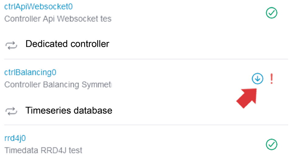
|
You can use the scroll bar to examine the origin of the warning or error in more detail. |
|
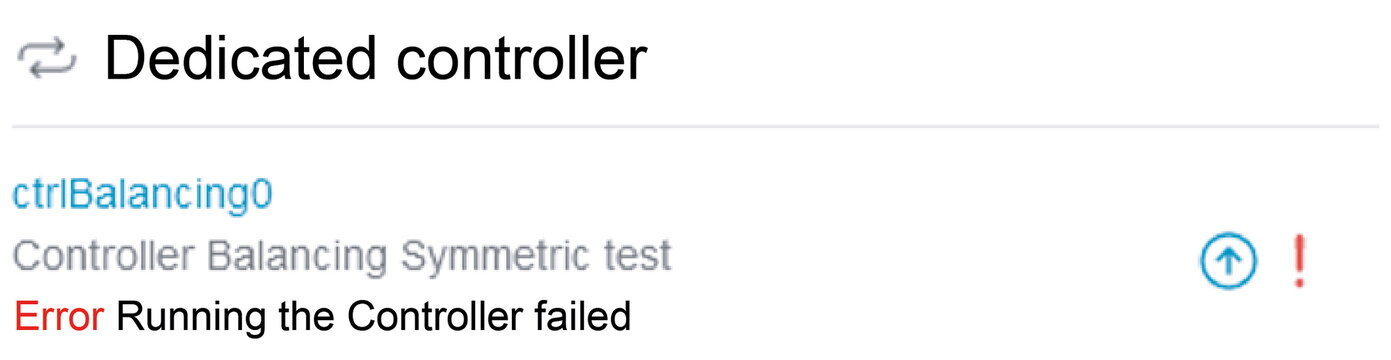
Clicking on the icon (down arrow) displays a more detailed error description depending on the error. |
In the example above, an incorrect reference for the grid meter was intentionally entered for test purposes, which is why the controller fails to run.
The FENECON service must be contacted to rectify errors.
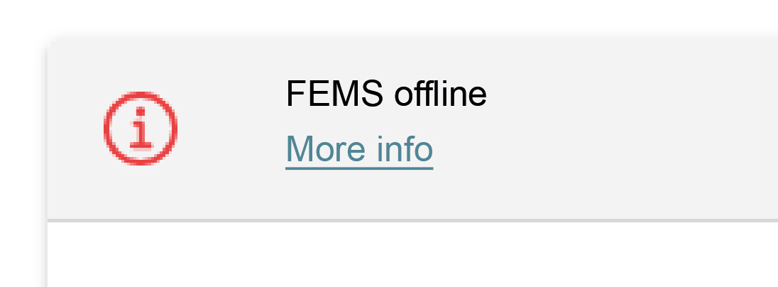
|
Under certain circumstances it can happen that the FEMS is not accessible and the adjacent error message appears. |
|
These instructions only contain work that can be carried out without specialist knowledge of the manufacturer. |
|
Work that is not described may only be carried out by authorized service personnel. Contact customer service to change parameters and programs |
If the energy storage system malfunctions, contact the FENECON Service:
Phone: +49 (0) 9903 6280 0
E-mail: service@fenecon.de
9.1.3. Details for the FENECON Service
The following information must be provided for the FENECON Service:
-
Device type/configuration.
-
FEMS number.
-
Currently installed software version.
-
Ticket number from previous faults (if available).
-
Error code of the inverter (if available).
The information can be found on the type label and in the system profile in Online Monitoring.
10. Technical maintenance
10.1. Tests and inspections
Residual risks:
|
When carrying out inspection work, ensure that the product is in a safe condition. Improperly performed inspections can have serious consequences for people, the environment and the product itself. |
|
Inspection work must only be carried out by trained and qualified specialists. |
Check the product and the cables regularly for visible external damage. If components are defective, contact the FENECON Service. Repairs must only be carried out by a qualified electrician.
|
The respective maintenance instructions must be observed for all individual components.
|
10.2. Maintenance work
Residual risks:
|
During maintenance work, troubleshooting and assembly activities, ensure that the product is switched off in a safe manner and secured against being switched on again. Improperly performed maintenance and servicing activities can have serious consequences for people, the environment and the product itself. |
|
Before carrying out maintenance work on systems which could be under pressure or in which very hot/hazardous substances could still be present:
|
|
The product may only be serviced by persons who have received detailed instruction on the subject. |
|
The frequency of use and environmental conditions may make it necessary to vary the intervals between the activities described below.
|
|
Maintenance work must only be carried out by trained and qualified specialists. |
11. Storage
|
Storage longer than 6 months
|
-
Do not store the energy storage system with flammable or toxic objects.
-
Store energy storage systems with safety defects separately from undamaged ones.
-
The SOC of the individual full packs of the energy storage system is ≥ 25 % SOC on delivery.
-
After 90 days, check the SOC; it should be in the range of 15-35 % SOC. If this is not the case, charge or discharge the batteries.
-
Recharging the full packs is recommended from 20 % SOC
Storage area: Fireproof indoors/outdoors with suitable weather protection
-
Air temperature: -20 °C to 40 °C.
-
Relative humidity: max. 50 % at +40 °C.
12. Utilization
The service life of the product depends on the service life and maintenance intervals carried out by specialist personnel. The service life is particularly influenced by preventive maintenance and servicing. Timely replacement of wearing parts and appropriate documentation of each activity is therefore crucial for the availability of the product.
All functional safety elements must be replaced in good time before the calculated or specified service life in accordance with the number of operating cycles or operating time specified by the manufacturer. However, all Functional Safety components should be completely overhauled after 20 years at the latest, in accordance with the applicable standard(s).
13. Transport
This section contains information on external and internal transportation of the product.
Transportation is the movement of the product by manual or technical means.
-
Only use suitable and tested lifting gear and hoists for transportation!
-
The product must only be transported using the means of transport specified by the manufacturer (see Transport procedure).
Residual risks:
|
Risk due to lifted loads!
|
|
Check that the parts and outer packaging are in perfect condition. |
|
Ensure that:
|
Legal regulations
The off-site transportation of the product is carried out in accordance with the legal regulations of the country in which the product is transported off-site.
13.1. Safety instructions
-
Transportation is carried out by a hazardous goods carrier.
-
The transportation of lithium-ion batteries "UN3536" is subject to the ADR regulations.
-
Hazardous goods labeling must be affixed to all sides of the container during shipping.
-
The current laws, regulations and standards must be observed when transporting the batteries (e.g. Hazardous Goods Transportation Act - GGBefG).
-
Upon receipt of the delivery, check it immediately for completeness and transport damage.
-
Use personal protective equipment (depending on the boundary conditions) (minimum requirement: hard hat and protective footwear)
-
The electrical connections must be disconnected before transportation.
-
Before lifting, check that the attachment points and lifting gear are correctly seated.
-
The container should only be transported with a SoC of 30 %.
-
For correct transportation, an angle of 30°-45° of the lifting gear to the vertical must be maintained (see image forklift and crane pick-up points).
-
The load capacity must be dimensioned so that the mass of the product can be safely absorbed (see Dimensions and [Weight]).
-
The size of the transport surface must be dimensioned so that the product can be safely placed and secured on the transport surface.
13.2. Change of location
A relocation of the container after commissioning is not planned.
If a change of location is planned, FENECON GmbH must be consulted beforehand.
In the event of a change of location, the container can be transported using a suitable industrial truck or hoist.
13.3. Transport procedure
Required aids
The following equipment is required for safe off-site transportation:
-
Loading and unloading: With the aid of a forklift truck or crane.
-
Transportation: Only by motor vehicle for road transport.
Lifting the container
-
Pick up and load the container either with a hoist (e. g. crane) or a forklift at the lifting points provided (see image Forklift and crane lifting points).
|
During this process, observe the weight specifications in the transport documents (see [Weight]). The following lifting instructions must be observed under all circumstances to protect the container from damage. |
Lifting instructions
-
A fork length of at least 1200 mm is required for transportation with a forklift truck.
-
For correct transportation, maintain an angle of 30°-45° (see image Forklift and crane pick-up points).
-
Information on weight, center of gravity and dimensions can be found in the sections Dimensions and [Weight].

-
Place the Industrial S on the means of transport and secure it. The transport crossbars/transport securing devices on the roof can be used to secure the load.
14. Dismantling and disposal
Residual risks:
|
Incorrect operation |
|
Incorrect operation can lead to material damage.
|
14.1. Safety instructions
-
Wear the following suitable PPE for all work:
-
Protective footwear
-
Protective gloves, cut-resistant if necessary
-
Protective eyewear
-
-
The storage system may only be dismantled by authorized electricians
-
Dismantling work must only be carried out when the system has been taken out of operation.
-
Before starting disassembly, all components to be removed must be secured against falling, tipping over or moving.
-
Dismantling work must only be carried out when the system is shut down and only by service personnel.
-
Use transport aids. Use existing attachment points for transporting the system parts.
-
The dismantling instructions of the component manufacturer (see 16.1 Applicable documents) must be observed.
-
The batteries are removed by service personnel and transported by a hazardous goods carrier.
-
When transporting the battery modules, the current laws, regulations and standards must be observed (e.g. Hazardous Goods Transportation Act - GGBefG).
14.1.1. Prerequisites
-
The power supply to the Battery energy storage unit is interrupted and secured against being switched on again.
-
The operator’s information technology equipment has been dismantled and removed.
|
Injuries to the body or limbs due to sharp edges and points on parts of the system
|
14.2. Waste disposal
|
After proper disassembly, the dismantled individual parts must be recycled:
-
The electrical energy storage system must not be disposed of with normal household waste.
-
Scrap metallic material residues.
-
Recycle plastic elements.
-
Dispose of the remaining components sorted according to material properties.
Electrical waste, electronic components, lubricants and other auxiliary materials are subject to hazardous waste treatment and may only be disposed of by authorized specialist companies.
The following points must also be observed when disposing of the machine or its components as well as the operating and auxiliary materials:
-
Comply with national regulations on site
-
Observe company-specific specifications
-
Dispose of operating and auxiliary materials in accordance with the applicable safety data sheets
-
The packaging material must be disposed of in an environmentally friendly manner
-
Do not expose the battery modules to high temperatures or direct sunlight
-
Do not expose the battery modules to high humidity or corrosive atmospheres
-
For special instructions on the disposal of used batteries, please contact the FENECON Service.

16. Applicable documents
|
All supplier components can be requested from the manufacturer. |
| Nr. | Komponente | Herstellerdokumente |
|---|---|---|
1 |
KACO gridsave 92.0 kVA |
Online verfügbar: |
2 |
Klimaaggregat Hydac 4 kW |
In Zubehör-Box enthalten: |
3 |
KDK 2PU CT Netzzähler |
In Zubehör-Box enthalten: |
4 |
Roxtec - Kabeleinführung |
Online verfügbar: |