Installation and Configuration Manual — KEBA KeContact P30 c-series
1. Introduction
1.1. Legal provisions
The information contained in these documents is the property of FENECON GmbH. Publication, in whole or in part, requires the written consent of FENECON GmbH.
Subject to changes and printing errors!
1.2. Qualification of the installing electrician
A qualified electrician is a person who has the necessary experience and training:
-
Setting up, switching on, switching off, disconnecting, short-circuiting and repairing circuits and devices
-
Standard maintenance and use of protective devices in accordance with current safety standards
-
First aid/emergency care
-
Current knowledge of local regulations, standards and guidelines
3. Commissioning

|
To install the KEBA charging station, please follow the instructions in the "KeContact KC-P30 Charging Station Installation Manual." |
|
|
You should also read and familiarize yourself with the "Configuration Manual" for the x-series: |
|
This quick guide refers to the original user manuals. |
3.1. Ethernet connection
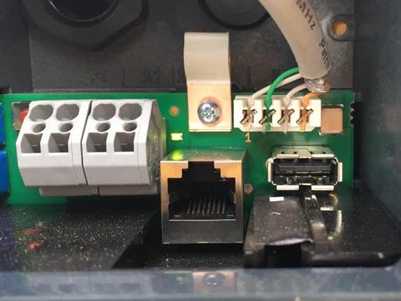
The network connection is made via the LSA terminal block X4.
|
Please note that the Ethernet connection X3 (here: RJ45) was designed as a service port. This is not suitable for a permanent, stable connection to the FENECON Energy Management System. |
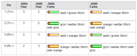
To connect to the LSA terminal block X4, the network cable must be disconnected and the cables need to be connected to pins 1-4.
The assignment type of the customer network must be observed.
There are two ways in which your KEBA KeContact P30 c-series can obtain an IP address. The setup via static IP address or via DHCP is described below.
|
In a network, IP addresses are typically assigned automatically via DHCP. In many cases, this is handled by the internet router, e. g. a FRITZ!Box. This can cause communication between the FEMS and the charging station to fail. To prevent this, IP addresses can be set to static values. |
3.2. Assigning an IP address via DHCP
|
We recommend setting up via a DHCP server (here: Dynamic Host Configuration Protocol) from the second charging station onwards. |
After connection to the customer network, the wallbox is assigned an IP address using DHCP. This IP address can be determined in the DHCP server, e. g. the router, or can be read on the display when the wallbox is started.
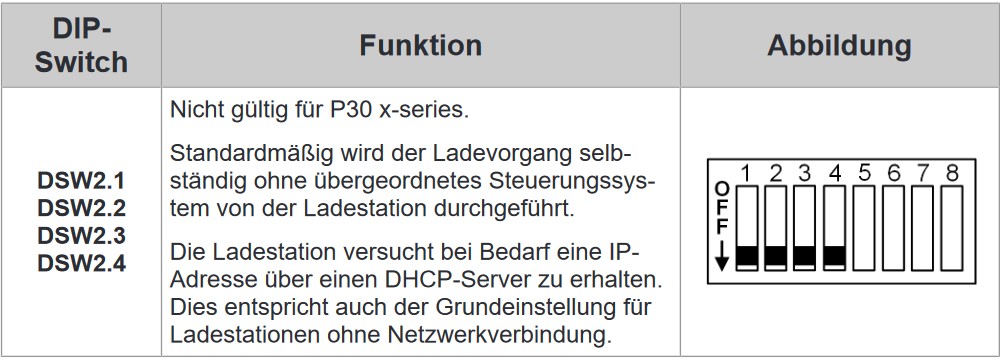
| An IP address can only be assigned via DHCP if the DIP switches of the second switch panel D2.1 to D2.4 are set to "OFF". |
To be able to access the wallbox via its IP address for testing purposes, your computer must be in the same network. Open an internet browser and enter the IP address identified.
Example: http://123.123.123.123
After entering your login data (included in the scope of delivery), a website opens that looks like this:
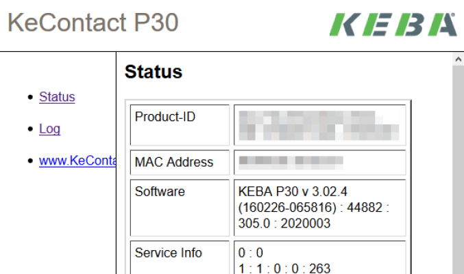
The web interface of the KEBA c-series provides access to status information, e. g. the total energy charged. This web interface can only be used for reading, no configurations or settings can be made here.
3.3. Configuration of the DIP switches
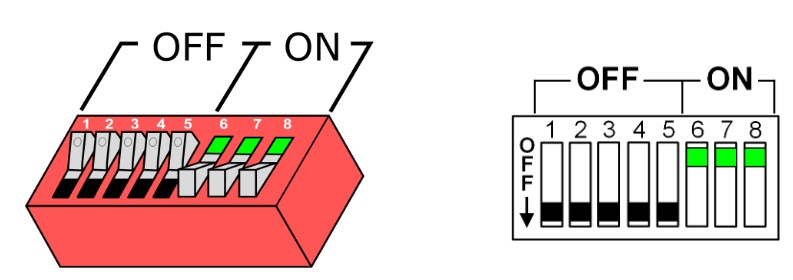
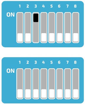
Various settings such as IP assignment and control can be made via the DIP switches. In the following illustration you can see the two positions of the switches.
The DIP switches can be accessed by removing the front cover. Here you will find two different switch panels, which we will explain in more detail below.
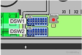
We differentiate here between the top panel "DSW1" and the bottom panel "DSW2".
3.3.1. Setting the charging station control functions
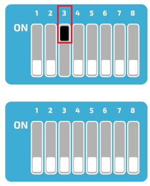
The first three DIP switches on the upper DSW1 panel are used to control and forward signals from the charging station.
Of these three switches we only need D1.3, which is used to activate the SmartHome interface via UDP, allowing the FEMS to set the charging specifications for the charging station via the UDP protocol. D1.1 and D1.2 remain in the "OFF" position.
3.3.2. Setting the permissible amperage
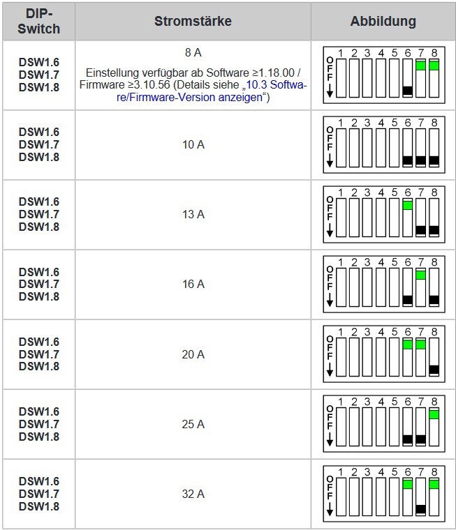
DIP switches D1.6 - D1.8 are used to set the permissible current, which determines the maximum charging power of the charging station, provided the vehicle to be charged supports this charging power.
3.3.3. More DIP switches
However, all other DIP switches have no function in conjunction with the FEMS or can influence the connection, e. g. D2.8.
Therefore they remain in the "OFF" position after commissioning.
3.3.4. Charging network
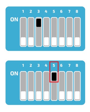
The Keba KeContact P30 c-series can be used as a slave in a charging network with a Keba KeContact P30 x-series. In this case, the x-series takes over the management of the RFID authorization. To enable communication between the charging stations, the DIP switch D2.5 must be activated on all charging stations (x-series and c-series). In addition, the c-series must have received a dynamic IP address from the DHCP server. If there is no charging network (only one charging station is available), the DIP switch D2.5 does not need to be activated.
3.4. § 14a of the Energy Industry Act (EnWG)
From 01/01/2024, all wallboxes & charging stations in the private sector must be controllable by the grid operator in accordance with § 14a of the German Energy Industry Act. Depending on the manufacturer, your wallbox can be dimmed to the required 4.2 kW charging power and/or switched off for the required period of time.
| Currently, the proper dimming of wallboxes & charging stations is not achieved via the FENECON energy management, but via solutions provided by the wallbox manufacturers. |
Prerequisites
All §-14a-compliant KEBA KeContact Series that can be integrated into the FEMS Online Monitoring are listed below.
Wallbox model type |
§-14a compliance (e. g. dry contact X1, Modbus TCP, OCPP) |
|---|---|
KEBA KeContact P30 X-Series |
|
KEBA KeContact P30 C-Series |
|
KEBA KeContact P40 |
| A KEBA KeContact can currently be properly integrated into the FENECON Energy Management System via the potential-free contact X1. |
Connection of the control box
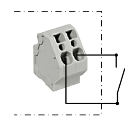
The device is configured via the potential-free contact X1 of the compatible KeContact charging station.
Connect the control box to the input and output terminals of the potential-free contact X1 as shown in the [Circuit diagram for the potential-free contact X1].
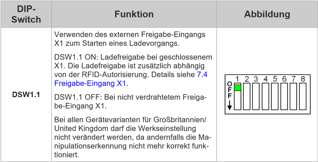
To enable control by external components (here: control box), the DIP switch D1.1 must be set to "ON".
The wallbox then needs to be restarted.
Setting up the EnWG-compliant amperage
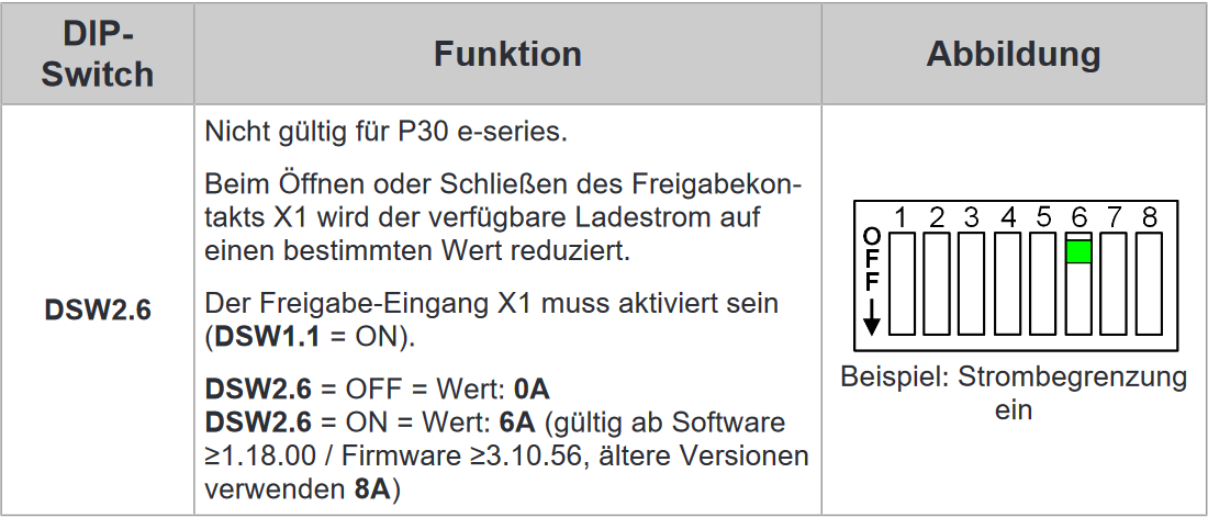
From software version 1.18 or firmware version 3.10.56, the available charging current for the KeContact P30 series can be set to 0 A or 6 A in accordance with EnWG using the DIP switches.
|
In software version 1.17.2, the EnWG-compliant current was preset to 8 A. For more information, please refer to the KEBA KeContact manuals or the KEBA KeContact FAQ . |
To reduce the charging current to a specific value, set DIP switch D2.6 to the desired position.
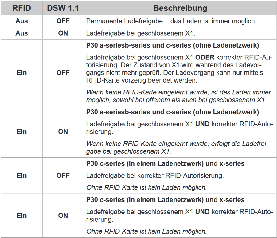
| Activating DIP switch D1.1 results in new dependencies for starting a charging process using RFID authorization. |
The configuration is now complete.
4. Install FEMS App KEBA KeContact P30 c-series
In the FEMS App Center you will find all installable FEMS Apps — such as the FEMS App KEBA KeContact P30 c-series.
|
The user manual FEMS App Center provides detailed instructions on how to use the FEMS App Center. It also explains how to register and redeem a license key. |
Then follow the instructions in the FEMS App installation wizard on your KEBA KeContact P30 c-series.
4.1. Installation wizard
You will then be taken to the installation wizard for FEMS App KEBA KeContact P30 c-series.
|
Please select the correct series for your KEBA KeContact under Product series. |
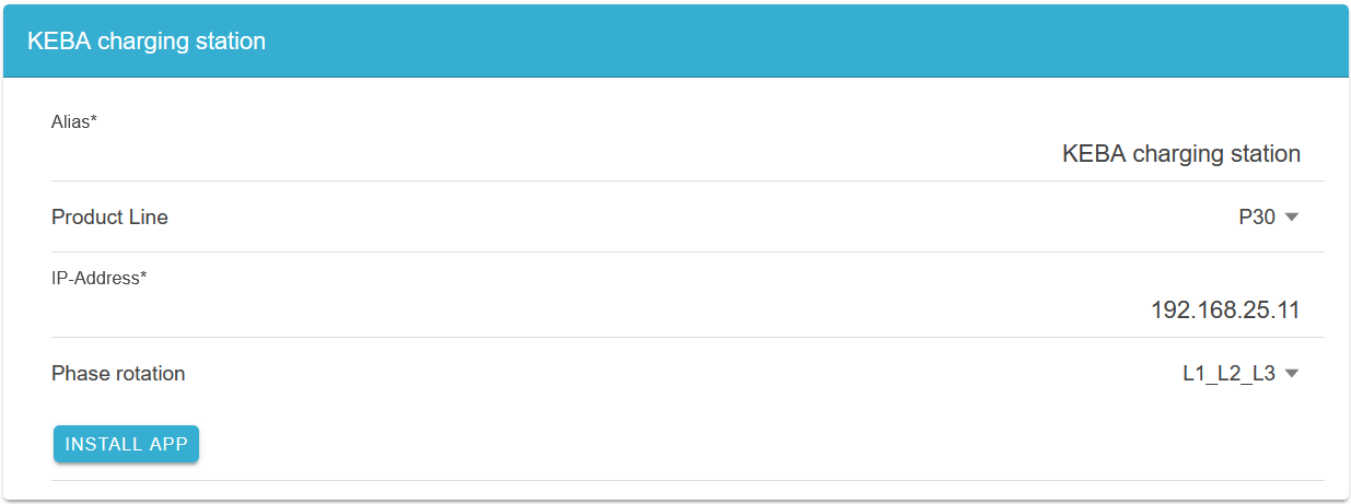
The KEBA KeContact P30 Series is selected as standard.
Some of the input fields are pre-filled. Nevertheless, enter your data if it differs from the default values (e. g. IP address). Otherwise, the default values can be retained (e. g. port, Modbus unit ID).
| Mandatory fields are marked with * |
| Check your entries and make sure that they are correct. Otherwise the respective app will not work properly! |
In the next step, you can set a phase rotation.
|
Please note that phase rotation is only included from FEMS release 2024.11.2 or later. |
The phase connection L1_L2_L3 is selected as standard.
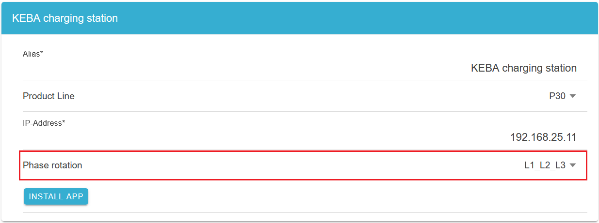
If your phase connection differs from this, you can select a different phase connection using the drop-down button.
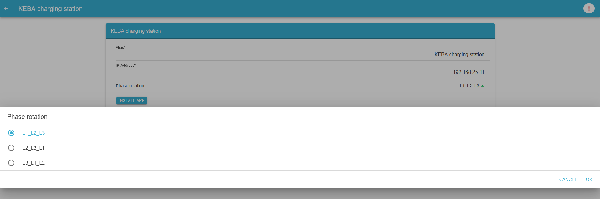
Confirm with "OK".
Then click on "Install app".
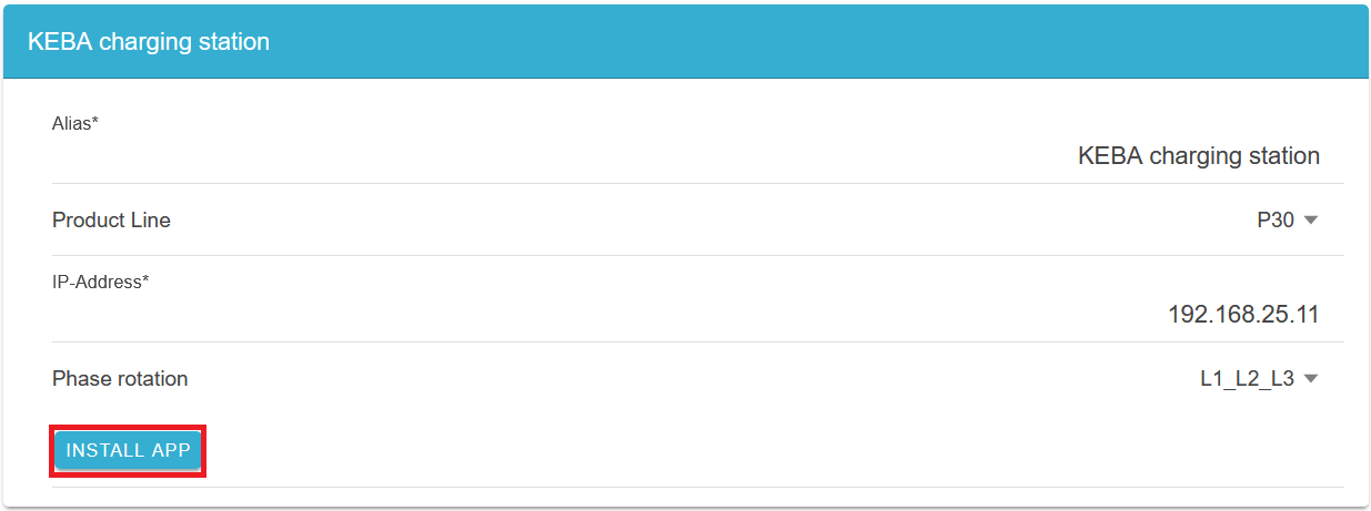
Once the installation process is complete, the new app appears in the overview of the FEMS App Center in the "Installed" category.
The FEMS App KEBA KeContact P30 c-series has been successfully installed.
4.2. Edit FEMS app
|
Apps that have already been installed can be edited later to change their configuration settings. To do this, select the app in the FEMS App Center overview and click the "Edit App" button. Detailed instructions can be found in the App Center User Manual: https://docs.fenecon.de/en/fems/app_center/App_Center.html#_fems_app_bearbeiten. |