Installation and Operating Manual FENECON Industrial L
1. About these instructions
These operating instructions are an integral part of the battery energy storage system and must be kept in its immediate vicinity and accessible to personnel at all times. Furthermore, all documents listed in the appendix to these operating instructions and the operating instructions of the component manufacturers must be observed.
Personnel must have carefully read and understood these operating instructions before starting any work.
1.1. Manufacturer
FENECON GmbH
Gewerbepark 6
94547 Iggensbach
Germany
Phone +49 (0) 9903 6280 0
Fax +49 (0) 9903 6280 909
E-mail: service@fenecon.de
Website: www.fenecon.de
1.2. Formal information on installation and service instructions
© FENECON GmbH, 2025
All rights reserved.
Reprinting, even in part, is only permitted with the permission of FENECON GmbH.
1.3. Version/revision of the installation and service instructions
| Version/Revision | Änderung der Betriebsanleitung | Datum | Name |
|---|---|---|---|
V0 |
Entwurf Ersterstellung |
23.05.2023 |
FENECON GmbH |
V20240209 |
Freigabe |
09.02.2024 |
FENECON GmbH |
V20241001 |
Veröffentlichung auf docs.fenecon.de |
30.09.2024 |
FENECON PM |
V2024.11.28 |
Ergänzung der BMA, Baustand AA5 und der Variante der fertig bestückten Auslieferung |
28.11.2024 |
FENECON MR |
1.4. Symbol conventions
Representation |
Meaning |
"Highlighting" |
Highlighting special terms in the text |
[push-button] |
Operating and display element (e. g. push-button, signal light) |
>>button<< |
Button and visualization (e. g. push-button, signal light) |
→ |
Reference to sections/chapters of these instructions or to Applicable documents (→ section Technical data) |
|
||
|
||
|
||
|
||
|
1.5. Structure of warning notices
If observed, warnings protect against possible personal injury and damage to property. The signal word to classifies the magnitude of danger.
Warnings are structured according to the SAFE method:
| Signal word | Meaning |
|---|---|
S |
Signal word (DANGER, WARNING, CAUTION or NOTE) |
A |
Type and source of danger |
F |
Consequence |
E |
Escape |
|
Source of the danger
|
1.6. Terms and abbreviations
The following terms and abbreviations are used in the installation and service instructions:
| Term/Abbreviation | Meaning |
|---|---|
AC |
Alternating Current |
ADR |
Accord européen relatif au transport international des marchandises dangereuses par route |
Slide-in battery modules |
Steel frame in which 3 battery modules are installed and wired. |
Fire detection system |
Fire alarm system |
BMS |
Battery Management System |
FACP |
Fire alarm control panel |
CMB |
Current Measurement Board |
CSC |
Cell Supervisor Circuit |
DC |
Direct Current |
EMS |
Energy Management System |
EVU |
Energy Supply Company |
FEMS |
FENECON Energy Management System |
IBN |
Commissioning |
MCB |
Circuit breaker |
GCP |
grid connection point |
NC |
Normally Closed (NC) — normally closed/ normally closed contact |
NMC |
Nickel-Manganese-Cobalt |
PE |
Protective conductor |
PV |
Photovoltaic |
RCD |
Residual Current Device — Residual current device |
RTE |
Round-Trip-Efficiency — System efficiency |
SoC |
State of Charge — State of Charge |
VDE |
German Association for Electrical, Electronic & Information Technologies e. V. |
Widget |
Component of Online Monitoring |
1.7. Appendix to this document
All documents listed in the appendix to these installation and service instructions must be observed.
See section: Applicable documents.
1.8. Availability
The operator must keep these installation and service instructions or relevant parts of them within easy reach in the immediate vicinity of the product.
If the product is handed over to another person, the operator shall pass these installation and service instructions on to that person.
1.9. Scope of delivery
| Item | Component | Amount | Comment |
|---|---|---|---|
1 |
Container incl. climate control unit + cabling and optional fire detection system |
1 |
|
2 |
Inverter — KACO bp 92.0 TL3-S |
8 |
|
3 |
Inverter rack |
1 |
|
4 |
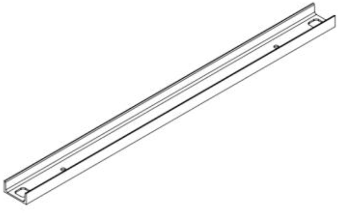
Transport rail |
2 |
Back to FENECON |
Variant — Fully equipped |
|||
7 |
Help |
4 |
Back to FENECON |
Further instructions for individual components of the storage system (e. g. inverters) can be found on the FENECON website in the Download Center.
2. Safety
2.1. Intended use
The FENECON Industrial L is an industrial energy storage system consisting of various modules. In particular, these include efficient inverters, the FENECON energy management system (FEMS) and slide-in battery modules including BMS. The FENECON Energy Management System large-scale Industrial L system is offered with an inverter output of 736 kVA and a capacity of 1288 kWh. The energy storage system is used to store and supply electrical energy and is intended for connection to the 400 V/50 Hz low-voltage grid.
Any other use is not an intended use.
2.2. Field of application
The product is intended exclusively for use in the following areas of application:
-
Industrial sector
Any other use is not in accordance with the intended use.
2.3. Qualification of staff
Qualified personnel must be deployed for the intended use, installation and maintenance of the system. The area of responsibility, competence and supervision of the personnel must be precisely regulated by the operator.
2.3.1. Qualified electricians
Qualified electricians include persons who:
-
are able to carry out work on electrical systems due to their technical training, experience and knowledge of the relevant standards and regulations.
-
have been commissioned and trained by the operator to carry out work on electrical systems and equipment of the battery system.
-
are familiar with how the battery system works.
-
recognize hazards and prevent them by taking appropriate protective measures.
-
have access to all maintenance information.
2.3.2. Service staff
Work that goes beyond connecting the system must only be carried out by the manufacturer’s specialist personnel. Other personnel are not authorized to carry out this work.
Service personnel includes: Manufacturer personnel or specialist personnel instructed and authorized by FENECON GmbH who must be requested by the operator to work on the electrical energy storage system (e. g. assembly, repair, maintenance, work on the batteries, etc.).
2.4. Safety and protective devices
The safety devices must not be bypassed or switched off. Operating the electrical energy storage system without or with defective protective devices is prohibited. The safety devices must always be kept within easy reach and checked regularly.
2.4.1. Sheet metal covers
All access points to the electrical energy storage are closed with sheet metal covers. Access is only possible with tools. Only authorized specialist personnel must open the housing. During operation, only the sheet metal cover with the inscription "control cabinet" must be opened by personnel authorized by the manufacturer.
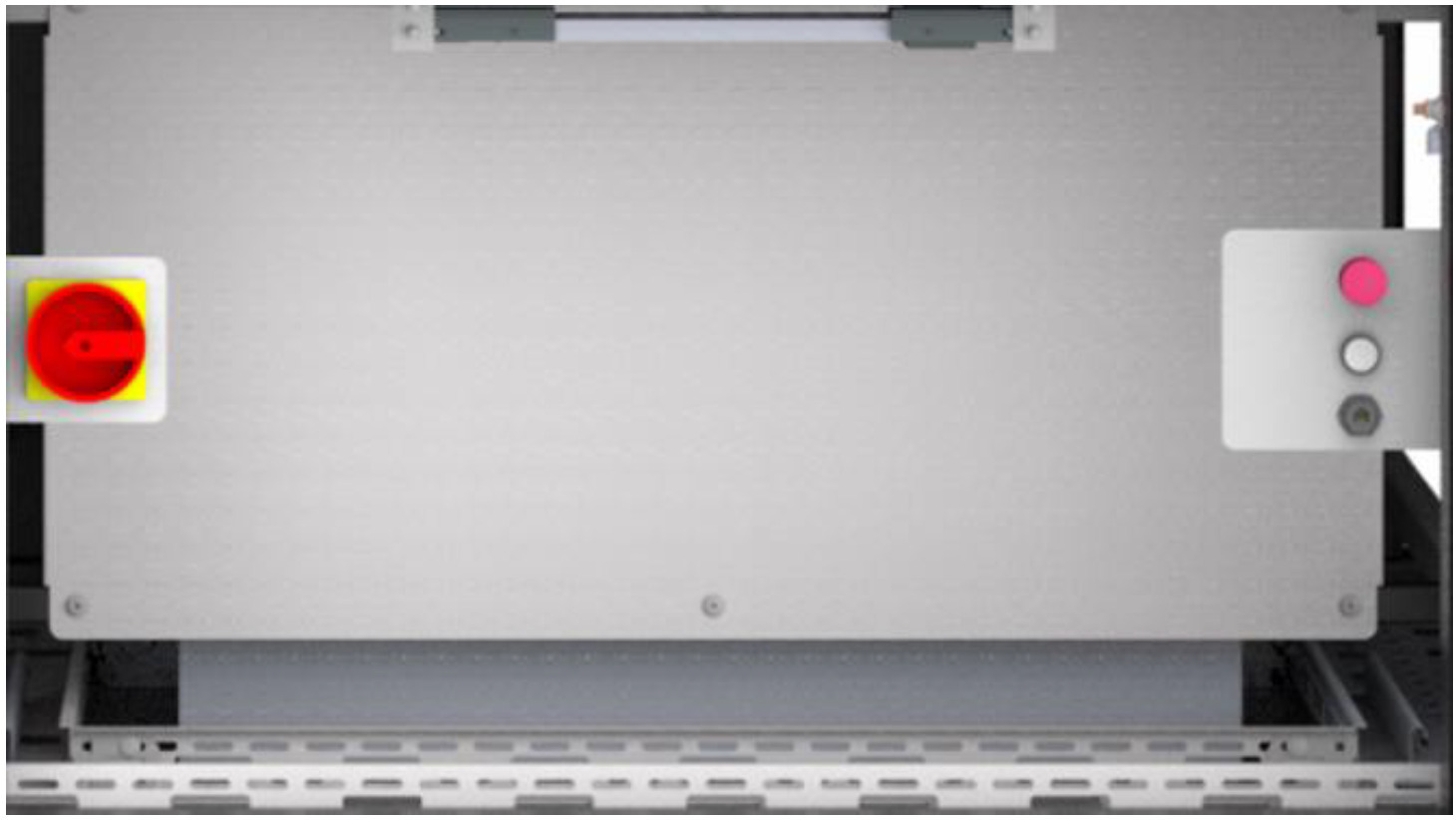
2.4.2. HV battery emergency off switch
The electrical energy storage system is equipped with an HV battery emergency off switch. The HV battery emergency off switch is located inside the electrical energy storage system. If required by the operator, there is the option of installing an external HV battery emergency off switch. Further information can be found in the Control Cabinet section. In emergency situations, the batteries can be switched off via the HV battery emergency off switch. The HV battery emergency off switch must not be used to switch off the batteries properly.
Pressing the emergency stop button
Pressing the emergency stop button triggers the following reaction:
-
The HV contactors in all batteries are forced open. This disconnects the battery voltage from the DC link.
Once the emergency situation has been rectified, the emergency stop push-button must be unlocked before the system is switched back on.
Unlocking the emergency-off push-button
The emergency-off push-button must be unlocked before switching back on after a tripped emergency-off:
Acknowledge emergency stop
The emergency stop is acknowledged at the acknowledge button on the emergency stop switch.
There is also the option of installing an external acknowledgement key; further information can be found in the section [Terminal assignment — Communication connection box].
2.4.3. Equipotential bonding inside/outside
The electrical energy storage unit has four equipotential bonding connections located at the bottom of the four corners. In addition, there are defined connection bolts inside the electrical energy storage unit where the equipotential bonding of the components must be established. For further information, please refer to the [assembly] section.
2.4.4. Optional fire alarm system
The FENECON Industrial L is available with an optional fire alarm system. This is installed and checked at the factory. Maintenance and service work on the fire alarm system may only be carried out by authorized specialist personnel.
In the event of an alarm or fault, contact the FENECON Service personnel.
To restart the system after a false alarm/fault, the fire detection system must be confirmed on site.
In the event of an alarm:
-
Break contact of the fire detection system triggers
-
Emergency-off switch of the electrical energy storage triggers
-
Fault report in Online Monitoring
-
Flashing light: Acoustic and visual signal
-
When connecting the customer’s own/external alarm system: alarm signal goes to the customer’s external FACP via potential-free contact
Connection to fire alarm control panel (FACP):
The fire detection system can be connected to an external fire alarm control panel. The connection allows alarm and fault signals to be transmitted to an operator FACP.
Potential-free contacts are available for connection to an external alarm panel:
-
1 x trigger/alarm
-
1 x malfunction of the fire alarm system
These can be found in the connection box on the back of the Industrial L:
| Item | = MEMORY + AKD - FA6 |
|---|---|
1 |
Terminal 1 → Fire alarm system: Relay alarm NO |
2 |
Terminal 2 → Fire alarm system: Relay alarm NC |
| Item | = MEMORY + AKD - FA7 |
|---|---|
1 |
Terminal 1 → Fire alarm system: Relay fault C |
2 |
Terminal 2 → Fire alarm system: Relay alarm C |
| Item | = MEMORY + AKD - FA8 |
|---|---|
1 |
Terminal 1 → Fire alarm system: Relay fault NO |
2 |
Terminal 2 → Fire alarm system: relay fault NC |
Connection cross-section (finely stranded, solid), min. 0.5 mm2 (AWG 26), max. 1.5 mm2 (AWG 16).
For more information, see the sections Junction box — Inverter and Terminal assignment — Communication connection box.
2.5. Residual risks
|
The product is manufactured in accordance with the current state of the art and recognized safety principles, taking into account the relevant legal regulations. |
|
No access for unauthorized persons! There is a risk of death or serious injury from unexpected incidents in the entire danger zone.
Safety: Ensure that no unauthorized persons are present in the areas. |
|
Danger of electric shock Contact with live components can lead to death or serious injury.
Work on live components may only be carried out by a qualified electrician. |
|
Danger of burning There is a risk of burns on hot cables and housing surfaces in the event of direct contact with uninsulated surfaces and hot media. The danger points are marked with corresponding pictograms.
|
|
Note This signal word indicates actions to prevent damage to property. Observing these instructions prevents damage to or destruction of the system. |
2.6. Safety instructions
2.6.1. General information on the FENECON Industrial L electrical energy storage system
-
The battery modules must only be removed or replaced by service personnel and transported in a hazardous area.
-
The current laws, regulations and standards must be observed when transporting the battery modules (e. g. Dangerous Goods Transportation Act (GGBefG, ADR)).
-
The electrical energy storage system must only be used under the specified charging/discharging conditions (see section Technical data).
-
Only use the battery modules as intended. Improper use can lead to overheating, explosion or fire of the battery modules.
-
Do not wet the area around the electrical equipment and batteries and avoid contact with water.
-
Prevent water ingress when working on the electrical energy storage system.
-
Keep away from water sources.
-
Do not crush, throw, drop or attempt to open the battery modules.
-
Switch off the battery module in question immediately and do not use it again.
-
Modifications to the battery modules are prohibited.
-
Set up/store the battery modules in cool places.
-
The electrical energy storage system must only be operated under the specified environmental conditions.
-
Do not use the battery modules if changes in color or mechanical damage are detected during assembly, charging, normal operation and/or storage.
-
Keep the electrical energy storage system away from children and animals.
-
Eye and skin contact with leaked electrolyte solution must be avoided. After contact with eyes or skin, rinse/clean immediately with water and seek medical attention. Delayed treatment can cause serious damage to health.
-
Do not short-circuit/bridge the slide-in battery modules.
-
Do not touch the battery module connectors (+) and (-) directly with a wire or metal object (e. g. metal chain, hairpin). In the event of a short circuit, excessive current can be generated, which can lead to overheating, explosion or fire of the battery modules.
-
Do not apply any mechanical force to the battery modules. The battery modules can be damaged and short circuits can occur, which can lead to overheating, explosion or fire of the battery modules.
-
No soldering work must be carried out on the battery modules. Heat introduced during soldering can damage the insulator and the safety venting mechanism and lead to overheating, explosion or fire of the battery modules.
-
The battery modules must not be dismantled or modified. The battery modules integrate a safety mechanism and a protective device, damage to which can lead to overheating, explosion and/or fire of the battery modules.
-
A battery module that exhibits odors and/or temperature increases, changes color and/or shape, leaks electrolyte solution or exhibits other abnormalities must be reported immediately to authorized service personnel and removed from the battery rack by them only, otherwise the battery module may overheat, explode and/or catch fire.
-
Do not charge the battery modules in an external charger.
-
Read the instructions for installation and operation to avoid damage due to incorrect installation/operation.
-
The battery modules may have insufficient cell voltage after a long storage period.
-
Do not expose the battery modules to high voltages.
-
Set up the electricity storage system on a level and load-bearing surface.
-
Do not place any objects on the battery modules.
-
Do not step on the battery modules.
-
The floor condition lies the responsibility of the operator.
2.6.2. Installation, operation and maintenance
Always observe the following safety instructions when installing, operating or maintaining the battery modules:
-
Installation/maintenance work on the battery modules and the electrical energy storage system and the establishment of cable connections may only be carried out by authorized qualified electricians.
-
During assembly and maintenance work on the battery rack, stand on dry insulating objects and do not wear any metal objects (e.g. watches, rings and necklaces) during maintenance work/operation.
-
Use insulated tools and wear personal protective equipment.
-
The battery modules can cause electric shock and burns due to short-circuit currents.
-
Do not touch two charged contacts with a potential difference.
-
Measure the battery voltage with a multimeter and ensure that the output voltage is 0 V in off mode.
-
If an anomaly is detected, the emergency off must be activated (if directly accessible).
-
Do not continue the maintenance work until the cause of the fault has been rectified.
2.6.3. Fire protection
-
The heat can melt insulation and damage the safety ventilation, which can lead to overheating, explosion or fire on the battery modules.
-
Do not heat the battery modules.
-
Do not expose the battery modules to direct sunlight.
-
Do not expose the battery modules to open fire.
-
Avoid contact between the battery modules and conductive objects (e. g. wires).
-
Do not install or use the battery modules near open flames, heaters or high-temperature sources.
-
Keep the battery modules away from sources of heat and fire, flammable, explosive and chemical materials.
-
Do not dispose of the battery modules in a fire due to the risk of explosion.
-
Do not store flammable materials in the container.
-
Only use flame-retardant operating fluids and coolants.
-
Clean extraction and ventilation systems regularly.
-
Change dirty filter elements.
-
Maintain free space around electrical energy storage.
-
Fire, open light and smoking in the installation area of the electrical energy storage is prohibited.
-
For optional fire detection system: Cleaning the intake pipes of the fire alarm system, maintenance of the system by authorized personnel.
2.7. In case of emergency
Proceed as follows in emergency situations:
-
Disconnect the electrical energy storage system from the grid.
-
Leave the zone of danger immediately.
-
Secure the zone of danger.
-
Inform those responsible.
-
Call a doctor if necessary.
2.8. Reasonably foreseeable misuse
All applications that do not fall within the scope of the intended use are considered misuse.
Work on live parts is generally not permitted. Electrical work may only be carried out by qualified electricians.
The following safety rules must be observed for all work on electrical components:
-
Disconnect.
-
Secure against restarting.
-
Check that there is no voltage.
-
Earth and short-circuit.
-
Cover or shield neighboring and live parts.
Non-compliance with the safety rules is considered a reasonably foreseeable misuse.
Other misuses include, in particular:
-
improper transportation, installation, assembly, trial operation or operation that may damage the product,
-
Change in the specified technical characteristics, including the individual components,
-
Change or deviation of the connected load,
-
Functional or structural changes,
-
Operating the product in a faulty or defective condition,
-
Improper repairs,
-
use by untrained persons (instruction in accordance with the installation and service instructions is provided by the operator),
-
operation without safety devices or with defective safety devices,
-
Disregarding the information in the original installation and service instructions,
-
Unauthorized access via the control unit or the network,
-
Fire, open light and smoking in the vicinity of the storage system,
-
Inadequate ventilation,
-
Unauthorized changes and actions to the electrical energy storage system,
-
Private use,
-
Use as mobile energy storage,
-
Direct use in a PV system (only one AC-side grid feed-in possible).
2.9. Pictograms
Pictograms on the system indicate dangers, prohibitions and instructions. Illegible or missing pictograms must be replaced by new ones.
| Piktogramm | Bedeutung | Position |
|---|---|---|

|
Warnung vor gefährlicher elektrischer Spannung |
Piktogramm am Gehäuse, und Kennzeichnung von Komponenten, bei denen nicht klar zu erkennen ist, dass sie elektrische Betriebsmittel enthalten, die Anlass für ein Risiko durch elektrischen Schlag sein können. |

|
Warnung vor ätzenden Stoffen |
Auf den Batteriemodulen |

|
Vor Benutzung erden |
Im Bereich der Erdungsanschlüsse (z. B. am Container) |

|
Getrennte Sammlung von Elektro- und Elektronikgeräten |
An den Batteriemodulen |

|
Warnung vor Handverletzungen |
|

|
Warnung vor heißer Oberfläche |
|

|
Allgemeines Warnzeichen |
|

|
Warnung vor Gefahren durch das Aufladen von Batterien |
| Piktogramm | Bedeutung | Position |
|---|---|---|

|
Allgemeines Verbotszeichen |
|

|
Keine offene Flamme; Feuer, offene Zündquellen und Rauchen verboten |
|

|
Kein Zutritt für Personen mit Herzschrittmachern oder implantierten Defibrillatoren |
|

|
Zutritt für Unbefugte verboten |
|

|
Anleitung beachten |
|

|
Kopfschutz benutzen |
|

|
Fußschutz benutzen |
|

|
Handschutz benutzen |
2.10. Operating materials/equipment
2.10.1. Electrolyte solution of the battery modules
-
Electrolyte solution is used in the battery modules (NMC).
-
The electrolyte solution in the battery modules is a clear liquid and has a characteristic odor of organic solvents.
-
The electrolyte solution is flammable.
-
The electrolyte solution in the battery modules is corrosive.
-
Contact with electrolyte solution can cause severe burns to the skin and damage to the eyes.
-
Do not inhale the vapors.
-
If the electrolyte solution is swallowed, induce vomiting.
-
Leave the contaminated area immediately after inhaling the vapors.
-
After contact with skin, wash thoroughly with soap and water.
-
After contact with eyes, rinse as soon as possible with running water for 15 minutes.
→ Consult a doctor immediately.
|
Further information on the electrolyte solution can be found in the manufacturer’s safety data sheet. |
2.10.2. Refrigerant of the cooling system
-
Contains pressurized gas, may explode when heated.
-
Protect from sunlight and store in a well-ventilated place.
-
Rapid evaporation of the liquid can cause frostbite.
-
Misuse or intentional inhalation can be fatal without alarming symptoms due to effects on the heart.
-
May cause cardiac arrhythmia.
|
The refrigerant used in the integrated air conditioning unit is R410a. |
2.10.3. Electrical equipment
-
Work on electrical equipment may only be carried out by qualified electricians.
-
Maintenance work may only be carried out by trained specialist personnel (service personnel).
-
Before starting work on the electrical energy storage system, visually check for insulation and housing damage.
-
Regular checks for insulation and housing damage must be carried out.
-
The system must never be operated with faulty or non-operational electrical connections.
-
To avoid damage, lay supply lines without crushing and shearing points.
-
Only insulated tools may be used for maintenance on uninsulated conductors and terminals.
-
Switch cabinets (e. g. inverter housing) must always be kept locked. Only authorized personnel with appropriate training and safety instructions (e. g. service personnel) should be allowed access.
-
The inspection and maintenance intervals for electrical components specified by the manufacturer must be observed.
-
To avoid damage, lay supply lines without crushing and shearing points.
-
If the power supply is disconnected, specially marked external circuits may still be live!
-
Dangerous residual voltages may still be present on some equipment (e. g. inverters) with an electrical intermediate circuit for a certain period of time after disconnection. Check that there is no voltage on these systems before starting work.
2.11. Notes on occupational health and safety
The obligations arising from occupational health and safety must be implemented by the operator of the low-voltage equipment.
Operator obligations in relation to the use of the product:
-
Making these installation and service instructions or extracts thereof available to persons who perform tasks with or in connection with the product.
-
Make the applicable documents available to these persons.
-
Instruction of persons with regard to the intended use as well as the prohibited use.
-
Instruction of persons with regard to safety devices and supplementary protective devices.
-
Instruction of persons with regard to all residual risks.
2.12. Personal protective equipment
Depending on the work on the system, personal protective equipment must be worn:
-
Protective footwear.
-
Protective gloves, cut-resistant if necessary.
-
Protective eyewear.
-
Protective headgear.
2.13. Spare and wear parts
The use of spare and wear parts from third-party manufacturers can lead to risks. Only original parts or spare and wear parts approved by the manufacturer may be used. The instructions for spare parts must be observed.
|
Request further information from the manufacturer. |
2.14. IT Security
|
FENECON energy storage systems and their applications communicate and operate without internet connection. The individual system components (inverters, batteries, etc.) are not directly connected to the internet or accessible from the internet. Sensitive communications via the internet are processed exclusively via certificate-based TLS encryption.
|
3. Technical data
3.1. General information
The FENECON Industrial L is an industrial energy storage system consisting of various modules. In particular, these include efficient inverters, the FENECON Energy Management System (FEMS) and slide-in battery modules including BMS. The large-scale FENECON Industrial L system is offered with a maximum apparent power of 736 kVA and a nominal DC capacity of 1288 kWh. The energy storage system is used to store and supply electrical energy and is intended exclusively for connection to the 400 V/50 Hz low-voltage grid.
3.2. System overview
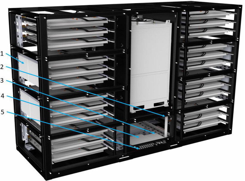
| Position | Component | Comment |
|---|---|---|
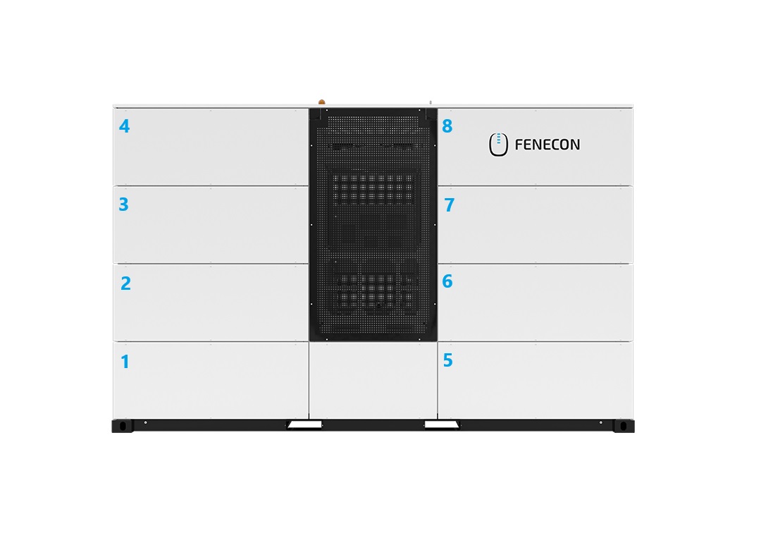
1 |
Slide-in battery module |
|
2 |
Climate control unit |
|
3 |
HV battery emergency stop panel |
HV battery emergency stop/acknowledgement key/RJ45 service port |
4 |
Control cabinet lighting with 230 V socket for e. g. service laptop |
|
5 |
Control cabinet |
|
6 |
Main switch |
|
7 |
Location: Optional fire detection system |
| Position | Component | Comment |
|---|---|---|
1 |
BMS box |
|
2 |
Water drain |
incl. drain strainer |
3 |
Communication connection box |
|
4 |
AC/DC connection box |
|
5 |
Cable gland plate |
3.3. Container including climate control unit and cabling
3.3.1. Dimensions
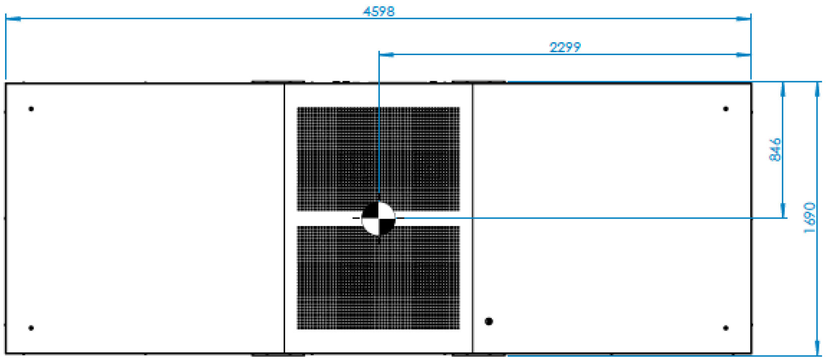
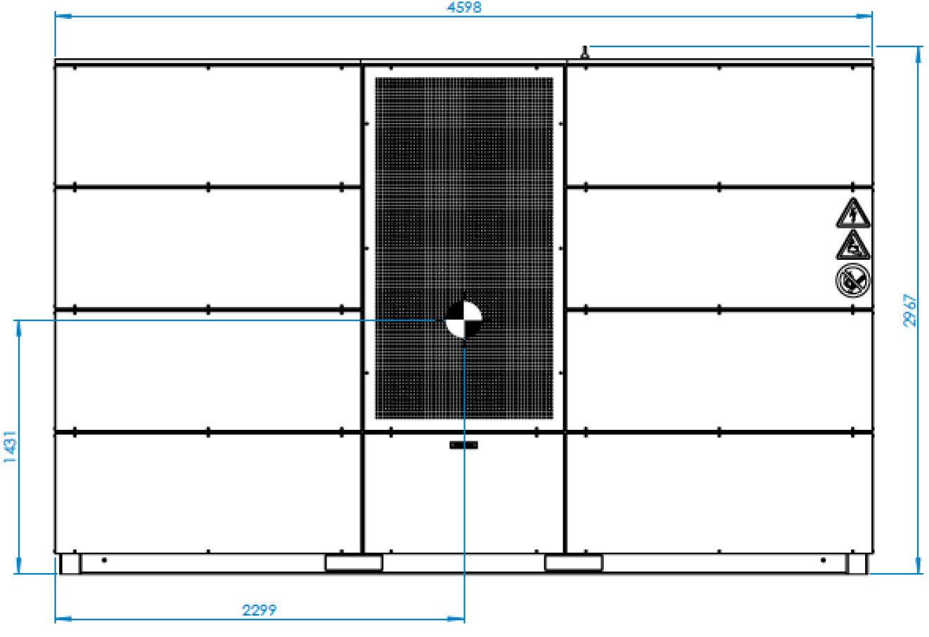
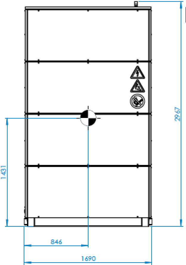
3.3.2. Mass
Container weight, fully-equipped |
10,600 kg |
Total lifting weight with lifting device |
11,000 kg |
3.3.4. Apparent power data
The apparent power of the storage system corresponds to max. 8 x 92 kVA plus 1 x 44 kVA. This results in a total of 780 kVA maximum apparent power at full load operation. The usable output is 736 kVA.
Fuse protection per control cabinet |
63 A |
DC fuse protection per inverter |
160 A |
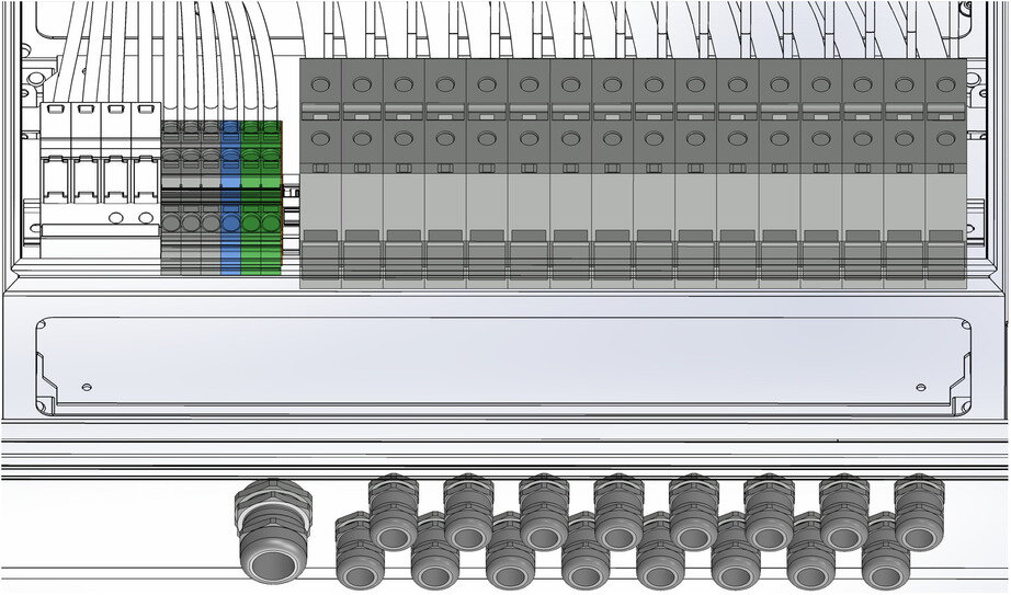
3.3.5. Control Cabinet
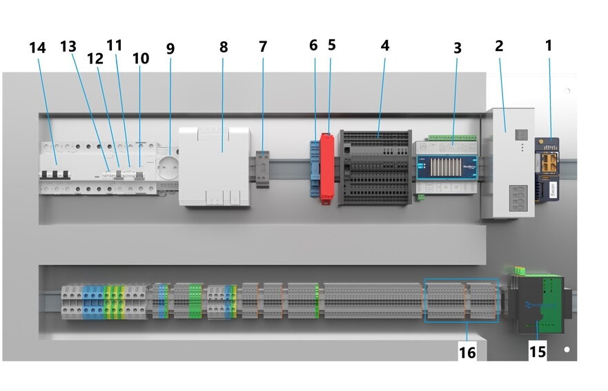
| Position | Component | Comment |
|---|---|---|
1 |
LTE router |
SIM card not included; Unlimited data volume required |
2 |
DC buffer (capacitive UPS) |
|
3 |
FEMS |
|
4 |
DC fuse unit and distribution |
|
5 |
Safety relay |
|
6 |
HV battery emergency stop reset relay |
Remote |
7 |
Disconnect terminal |
|
8 |
DC power supply unit |
|
9 |
Service socket |
incl. switch cabinet lighting |
10 |
Fault current circuit breaker service socket |
|
11 |
Control cabinet fan fuse |
|
12 |
DC power supply unit fuse |
|
13 |
Fault current circuit breaker climate control unit |
|
14 |
Air conditioning unit fuse |
|
15 |
Ethernet switch |
|
16 |
Connection terminals for optional fire detection system |
The following components are located on two offset panels in front of the control components:
Links:
-
Main switch
Right:
-
HV battery emergency-off push-button
-
Acknowledgement key
-
Service-Port
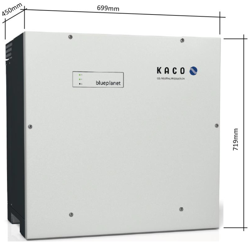
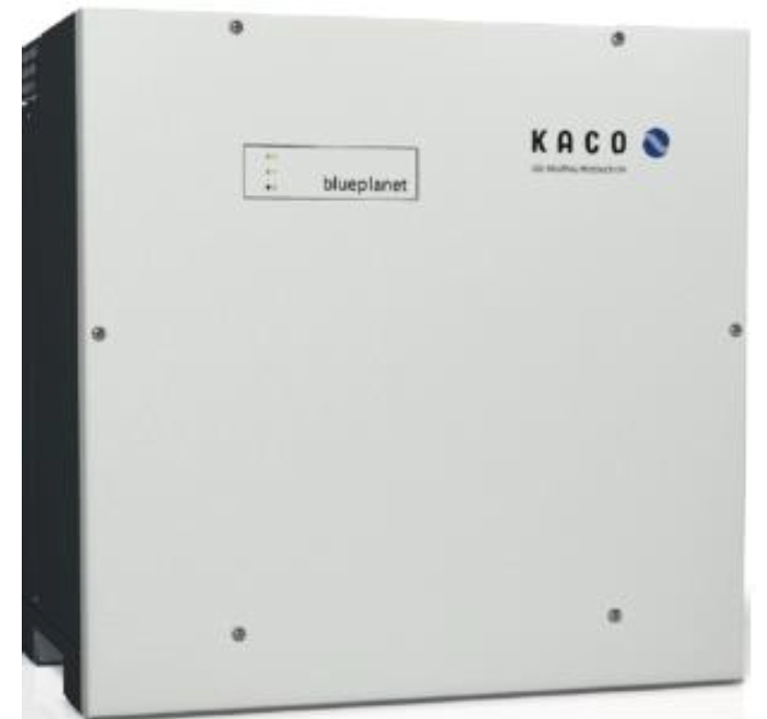
3.4. Inverter KACO blueplanet gridsave 92.0 — TL3-S
3.4.1. Battery Connection (DC) Battery
| Description | Value/dimension |
|---|---|
Battery charging and discharging voltage |
668 V to 1315 V |
DC input current, max. |
145 A |
3.4.2. AC grid connection
| Description | Value/dimension |
|---|---|
Rated power |
92,000 VA |
Rated voltage (Ph-Ph) |
400 V |
Rated voltage (Ph-N) |
230 V |
Voltage range (Ph-Ph) |
300 V to 580 V |
Rated frequency |
50 Hz/60 Hz |
Rated current AC |
3 x 132.3 A |
3.4.3. General information
| Description | Value/dimension |
|---|---|
Efficiency, max. |
charging: 98.5 %; discharging: 98.7 % |
Reactive power/cos phi |
0-100 % Smax/0.30 ind. to 0.30 cap |
Emergency power capable |
No |
Width | Depth | Height, approx. |
699 mm | 450 mm | 719 mm |
Operating temperature |
-20 °C to + 60 °C |
Protection class |
IP66/NEMA 4X |
Installation altitude above sea level |
3000 m |
Humidity |
0-100 % |
Weight |
80 kg |
Noise emission |
< 60 db (A) |
Installation |
Wall assembly |
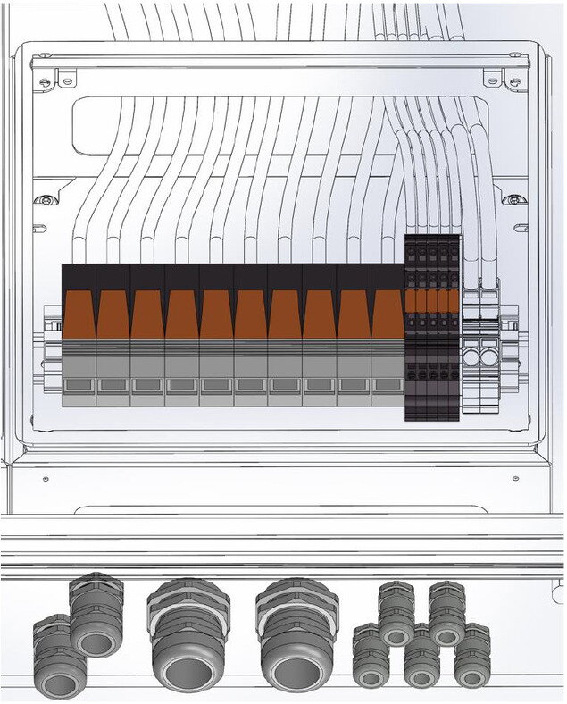
3.4.5. Junction box — Inverter
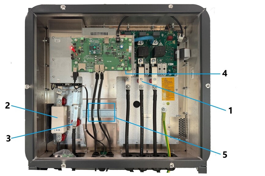
| Pos. | Description |
|---|---|
1 |
AC connection terminal |
2 |
DC fuse with connection terminal |
3 |
DC connection terminal |
4 |
INV OFF connection for remote control unit — used for the optional fire detection system. |
5 |
Place for junction box of optional fire detection system (2 pieces 3-wire feed-through terminals, 2.5 mm2, 24 A, gray) |
3.5. AC/DC connection box
The AC/DC connection box is located at the rear of the container, behind the cable glands. It is used to connect both the AC grid feed-in and the DC cables to the inverters.
The AC/DC connection box contains:
-
AC overvoltage protection.
-
AC connection terminals (3 phases/N/PE).
-
DC connection terminals.
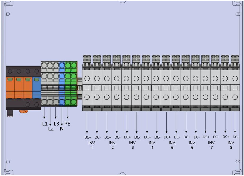
3.5.1. Terminal assignment — AC/DC connection box
| Description | Description |
|---|---|
L1 |
Phase conductor 1 |
L2 |
Phase conductor 2 |
L3 |
Phase conductor 3 |
N |
Neutral |
PE |
protective earth conductor |
DC+ WR1 |
DC+ for WR1 (max. cable diameter: AA1-3: 17 mm; AA4: 20.5 mm) |
DC- WR1 |
DC- for WR1 (max. cable diameter: AA1-3: 17 mm; AA4: 20.5 mm) |
DC+ WR2 |
DC+ for WR2 (max. cable diameter: AA1-3: 17 mm; AA4: 20.5 mm) |
DC- WR2 |
DC- for WR2 (max. cable diameter: AA1-3: 17 mm; AA4: 20.5 mm) |
DC+ WR3 |
DC+ for WR3 (max. cable diameter: AA1-3: 17 mm; AA4: 20.5 mm) |
DC- WR3 |
DC- for WR3 (max. cable diameter: AA1-3: 17 mm; AA4: 20.5 mm) |
DC+ WR4 |
DC+ for WR4 (max. cable diameter: AA1-3: 17 mm; AA4: 20.5 mm) |
DC- WR4 |
DC- for WR4 (max. cable diameter: AA1-3: 17 mm; AA4: 20.5 mm) |
DC+ WR5 |
DC+ for WR5 (max. cable diameter: AA1-3: 17 mm; AA4: 20.5 mm) |
DC- WR5 |
DC- for WR5 (max. cable diameter: AA1-3: 17 mm; AA4: 20.5 mm) |
DC+ WR6 |
DC+ for WR6 (max. cable diameter: AA1-3: 17 mm; AA4: 20.5 mm) |
DC- WR6 |
DC- for WR6 (max. cable diameter: AA1-3: 17 mm; AA4: 20.5 mm) |
DC+ WR7 |
DC+ for WR7 (max. cable diameter: AA1-3: 17 mm; AA4: 20.5 mm) |
DC- WR7 |
DC- for WR7 (max. cable diameter: AA1-3: 17 mm; AA4: 20.5 mm) |
DC+ WR8 |
DC+ for WR8 (max. cable diameter: AA1-3: 17 mm; AA4: 20.5 mm) |
DC- WR8 |
DC- for WR8 (max. cable diameter: AA1-3: 17 mm; AA4: 20.5 mm) |
3.6. Communication connection box
The communication connection box is located at the rear of the container, see illustration Components — Rear view. It provides both the communication interface to the inverters and the customer interface.
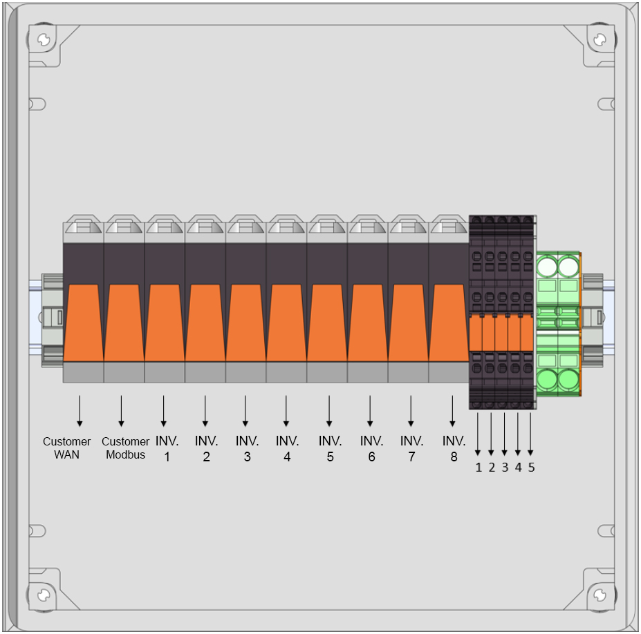
3.6.1. Terminal assignment — Communication connection box
| Item | Description |
|---|---|
WAN customer |
Overvoltage protection & interface to the customer WAN |
Modbus customer |
Overvoltage protection & interface to Modbus customer communication |
WR1 |
Overvoltage protection & interface network cable inverter 1 |
WR2 |
Overvoltage protection & interface network cable inverter 2 |
WR3 |
Overvoltage protection & interface network cable inverter 3 |
WR4 |
Surge protection & interface network cable inverter 4 |
WR5 |
Surge protection & interface network cable inverter 5 |
WR6 |
Surge protection & interface network cable inverter 6 |
WR7 |
Surge protection & interface network cable inverter 7 |
WR8 |
Surge protection & interface network cable inverter 8 |
1 |
Interface emergency stop acknowledgement (optional) |
2 |
Interface emergency stop loop 24 V (optional) |
3 |
Interface emergency stop loop GND (optional) |
4 |
Interface lighting emergency stop (not wired!) (optional) |
5 |
Modbus RTU interface (RS485) (optional) |
6 |
Interface for optional fire detection system Relay alarm NC/NO |
7 |
Interface for optional fire detection system Supply voltage relay alarm/fault |
8 |
Interface for optional fire detection system Relay fault NC/NO |
9 |
Interface for optional fire detection system Inverter enable |
3.7. Slide-in battery module (EB311 modules)
|
Storage/not charging the batteries for longer than 6 months
This must only be carried out by the manufacturer or by a company commissioned by the manufacturer. |
| Naming | Value/dimension |
|---|---|
Cell chemistry Nickel-manganese-cobalt |
Cell capacity |
188 Ah |
Cell configuration |
26s2p |
Nominal DC capacity |
53.7 kWh |
Nominal voltage slide-in module |
286,2 V |
Voltage range |
218.4 V to 327.6 V |
Maximum charge/discharge current |
400 A < 15 sec @ 23 °C, 50 % SoC |
Communication |
TPL |
Environmental temperature |
-20°C to +40°C |
Relative humidity (operation/storage) |
50% non-condensing (up to 90% permissible for short periods) |
Length | Width | Height |
1270 mm | 1260 mm | 120 mm |
Weight, approx. 250 kg |
Capacity guarantee |
see warranty conditions |
UN transport test standard |
UN38.3 |
3.8. Cable gland plate
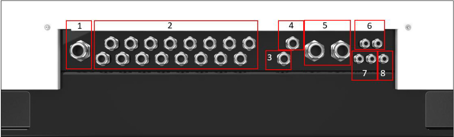
| Item | Description | Bolt connection | Clamping range (in mm) | Min. cable cross-section |
|---|---|---|---|---|
1 |
1 x cable gland AC supply |
M40 |
21-30 |
5 x 16 mm2 |
2 |
16 x cable gland DC inverter |
M25 |
12.5-20.5 |
1 x 50 mm2 |
3 |
1 x cable gland ModbusTCP customer interface |
M25 |
9-17 |
1 x 2 x 0.32 mm2 |
4 |
1 x cable gland internet |
M25 |
9-17 |
Cat6 |
5 |
2 x cable gland ModbusTCP for inverter (multiple insert for 4 cables each) |
M40 |
18-25 |
Cat6 |
6 |
2 x external emergency stop cable gland |
M16 |
4.5-10 |
2 x 1 mm^2 |
7 |
2 x cable gland for optional fire detection system |
M16 |
4.5-10 |
2 piece |
8 |
1 x cable gland ModbusRTU external |
M16 |
4.5-10 |
1 x 2 x 0.32 mm2 |
4. Assembly preparation
Residual risks:
|
||
|
4.1. Scope of delivery
The read and write access application is included as standard. Further software licenses for operating the system are not included in the standard scope of delivery. Furthermore, the applications Self-Consumption Optimization, Peak Shaving (phase-accurate) and Time Slot Peak Shaving can be purchased as options and can be installed both retrospectively and directly during commissioning.
The instructions for FEMS applications for the electrical energy storage system can be found at docs.fenecon.de.
4.1.1. Container including climate control unit and cabling
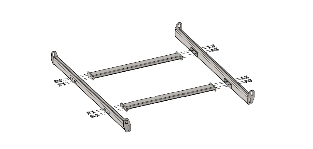
The battery storage system is delivered fully pre-wired. In addition to the cables, the container also contains the climate control unit, the control components and the connection boxes. In addition, the two profiles for securing the load and, in the case of a fully-equipped delivery, a lifting aid for crane transport in addition to the batteries are included in the scope of delivery.
| Illustration | Amount | Description |
|---|---|---|
|
1 |
Fully-equipped variant:
|
|
2 |
Transport rails |
|
1 |
Fully-equipped variant: |
4.1.2. Inverter KACO blueplanet gridsave 92.0 — TL3-S
| Abbildung | Anzahl | Bezeichnung |
|---|---|---|
|
8 |
Wechselrichter KACO blueplanet gridsave 92.0 — TLS-3 |
Handbuch |
1 |
Digitales Handbuch zur korrekten Montage der Wechselrichter |
4.1.3. Slide-in battery module (EB311 modules)
| Illustration | Amount | Description |
|---|---|---|
|
24 |
Fully-equipped variant: |
4.1.4. Accessories box
| Illustration | Amount | Description |
|---|---|---|
|
1 |
Manuals
|
|
1 |
Touch-Pen |
4.2. Tools/machines required
The following tools are required for assembly of the system components:
| Description | Comment |
|---|---|
Crane |
Fully-equipped variant: |
Multimeter |
|
Socket wrench set/ratchet box |
|
Socket wrench set |
|
Qualified electrician’s toolbox |
5. Assembly
The AC connections and inverters are assembled and installed by the operator. Please make an appointment in advance with your contact person at FENECON for the subsequent commissioning.
FENECON GmbH
Gewerbepark 6
94547 Iggensbach
+49 (0) 9903 6280 0
GERMANY
aftersales.industrial@fenecon.de
Residual risks:
|
||
Property damage due to condensation When the container is opened, moisture can enter the interior via the openings in the sheet metal covers. The condensate that forms can cause damage to the system. |
|
Note or photograph the serial numbers of the individual slide-in battery modules before assembly, as these must be documented later during commissioning (IBN protocol or IBN wizard). |
The following components must be installed or connected by the operator:
-
Container
-
Inverter rack (optional) and inverter
Before installation, carefully check whether the products are damaged and whether all accessories listed in the scope of delivery are included. If a part is missing or damaged, contact the manufacturer/dealer.
5.1. Select installation location
|
The operator of the system is responsible for selecting and preparing a suitable installation site for the energy storage system. It must be ensured that the ground is suitable for the use of a crane. The lifting instructions in the section must be observed when designing the crane and determining the lifting aids. In addition, sufficient clearance must be ensured in front of the container.
The industrial-scale electrical energy storage system FENECON Industrial L must be installed and operated outdoors.
5.1.1. Container
-
A minimum distance of 5 meters must be maintained at the front in order to have enough space to mount the slide-in battery modules with the forklift truck.
-
A minimum distance of 1 meter must be maintained at the rear to allow sufficient space for connecting the cables.
-
A distance of 1 meter must be maintained at the front to ensure access to the components at the side.
Before the container is unloaded, the correct foundations must be laid.
The substrate must have a suitable load-bearing capacity to ensure that the energy storage system is stable (e. g. point foundation, strip foundation, etc.).
There must also be an air gap between the base and housing to prevent corrosion.
Anti-slip mats (approx. 25 mm final height) at the corners under the electrical energy storage unit are suitable for this purpose.
This is also necessary in order to be able to easily dismantle the lifting device again.
The cable glands are located on the back of the container. The cables are fed out of the container through the cable glands.
5.1.2. Inverter
Für die Wahl des Aufstellortes der Wechselrichter muss das Handbuch auf der KACO-New-Energy-Website zu Hilfe gezogen werden. Zusätzlich zu dieser Anleitung muss vor den Wechselrichtern ein Mindestabstand von 1 Meter eingehalten werden, um Montage, Inbetriebnahme und Service gewährleisten zu können.
5.2. Assembly — Container
The electrical energy storage system with the slide-in battery modules is designed for outdoor use. In general, the [Select installation site] section must be observed when selecting the installation site.
5.2.1. Transport rail of the container (fully-equipped)
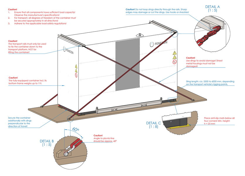
5.2.2. Depositing the container (fully-equipped)
Fully-equipped variant:
A crane must be used to deposit the container. The lifting instructions must be strictly adhered to! When setting down the container, place suitable anti-slip mats under all four corners (min. 25 mm final thickness).
5.2.3. Remove transport rails


After the transport rails have been removed, remove the protective film. Care must be taken to ensure that it is not damaged, as it remains the property of the manufacturer and must be returned.
Then, screw the seals back into the container. It is essential to apply a ceramic paste (e. g. WEKEM WS600) and tighten the bolts with a torque of 50 Nm.
Also remove the protective cap for the LTE antenna.

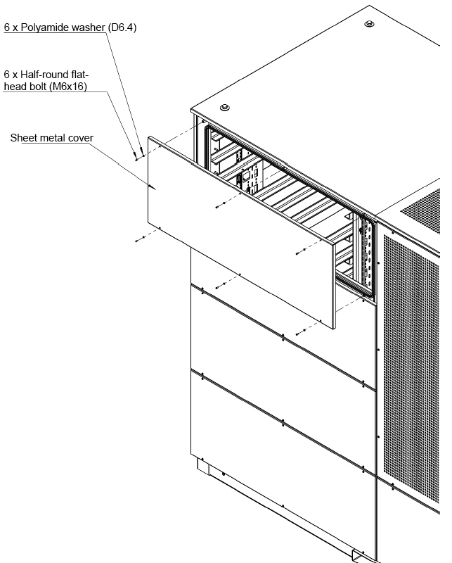
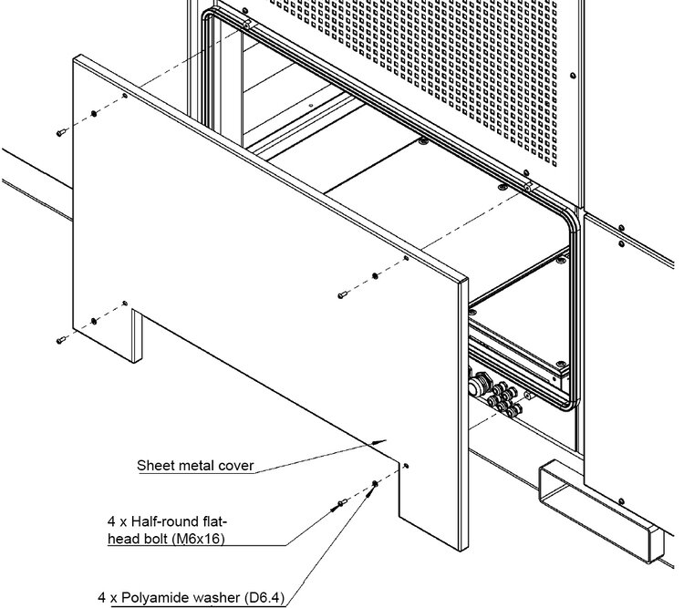
5.2.4. Disassembly — Sheet metal covers
The electrical energy storage tank is delivered completely sealed. Remove the corresponding sheet metal covers before commencing with the connection work.
The following sheet metal covers must be removed:
-
Connection/IBN: 2 x the small sheet metal covers under the climate control unit on both sides
-
8 x front on both sides of the climate control unit
→ Grease the threads before reassembling the sheet metal covers to ensure long-term accessibility of the bolt connection.
→ All positions of the sheet metal covers are numbered on both sides (on the electrical energy storage unit and on the sheet metal) to prevent them from being mixed up during assembly. All sheet metal covers must be earthed with the prepared earthing.
5.2.5. Installing the equipotential bonding of the container

It is possible to connect equipotential bonding at each corner of the electrical energy storage system. The electrical energy storage system must be integrated into the on-site lightning protection concept.
5.3. Assembly — Inverter rack (optional)
The inverter rack is included in the scope of delivery. The use of the inverter rack is optional. The inverters can be installed in all locations permitted for use.
To assemble the inverter rack, please follow the assembly instructions provided for this purpose.
5.4. Assembly — Inverter
For the safety instructions, assembly and installation location of the inverters, please refer to the following manual:
5.5. Assembly — Slide-in battery modules
In the "fully-equipped" variant, the batteries are assembled in the factory and connected on site exclusively by FENECON specialist personnel.
5.5.1. Wiring of the AC/DC connection box
|
The supply lines from the inverters to the container and the AC supply of the container must be designed by the customer, depending on the installation location of the inverters, and are therefore not included in the scope of delivery. |
Both the AC cables for supplying the climate control unit and the DC cables coming from the inverters are fed into the container through the cable glands in accordance with the section Cable gland plate.
They are then connected to the terminals as shown in the illustration in the AC/DC connection box section.
5.5.2. Wiring of the communication connection box
Insert the LAN cables coming from the inverters into the container through the cable glands as described in section Cable gland plate.
These are then plugged into the sockets as described in the [communication connection box] section.
-
Internet connection: To be able to guarantee a permanent data connection, an unlimited data volume is required.
Optional:
-
External Modbus communication
5.6. Assembly — Sheet metal covers
5.6.1. Install equipotential bonding
|
Protective conductor cables are already pre-assembled in the electrical energy storage unit and only need to be connected to the sheet metal covers at the marked points. |
-
A protective conductor must be fitted to each sheet metal cover:
6. Initial commissioning
The initial commissioning is carried out by FENECON GmbH. Please arrange an appointment for commissioning in advance with your contact at FENECON GmbH.
FENECON GmbH
Gewerbepark 6
94547 Iggensbach
+49 (0) 9903 6280 0
GERMANY
aftersales.industrial@fenecon.de
Residual risks:
|
||
|
7. FEMS — FENECON Energy Management System
7.1. Technical documentation — FEMS
The technical documentation of FEMS must be observed; this can also be found on the FENECON website at: www.docs.fenecon.de.
-
Internet connection
A permanent Internet connection for the FEMS is recommended and is necessary for commissioning. In principle, offline operation is also possible. In this case, however, the following functions cannot be used:
Remote commissioning, system updates, installation of new FEMS apps, transmission of measurement data to FENECON servers for remote access, use of Online Monitoring via the FENECON portal access (e. g. for on the go via smartphone), maintenance access for FENECON service employees, use of FEMS apps with third-party services via the internet (e. g. Time-of-use tariffs).
-
Network configuration
In the standard configuration, FEMS obtains the IP address via a DHCP server (e. g. FritzBox). The network configuration can also be adjusted in Online Monitoring under Settings & Network configuration. More information can be found here.
-
System update
The system is regularly updated as part of software updates. These updates can be installed via the Settings & FEMS system update tab.
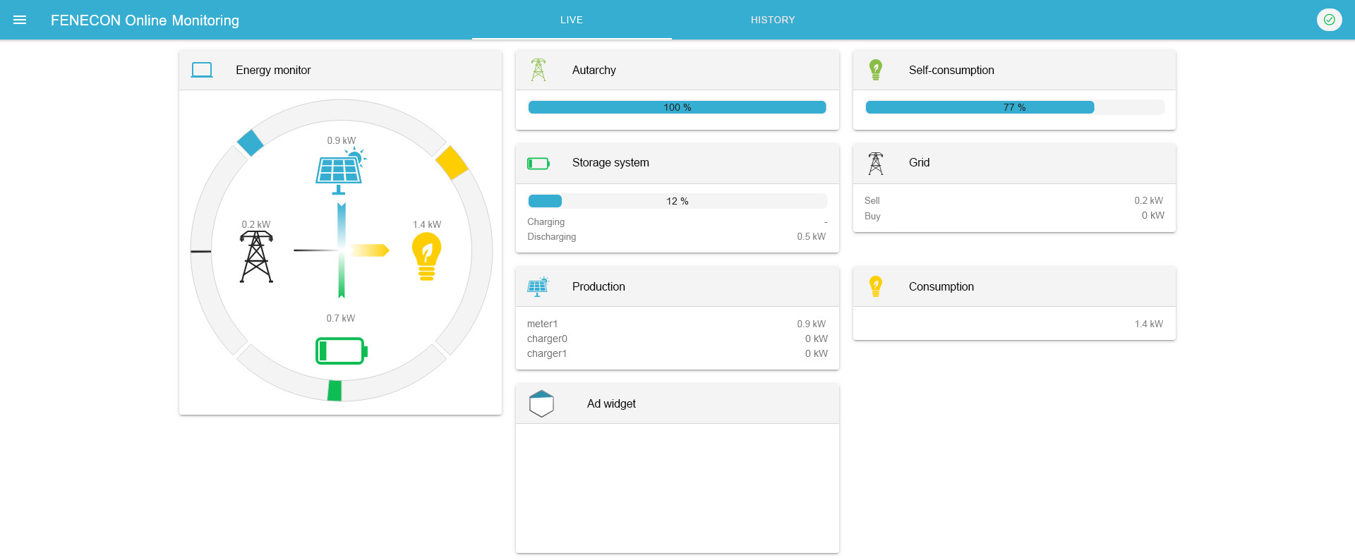
7.2. Online Monitoring
The FEMS Online Monitoring is used to visualize all energy flows in the system. The energy monitor shows live data on grid withdrawal or grid feed-in, PV production, charging/discharging of the battery storage system and electricity consumption. Other widgets show the percentage of self-sufficiency and self-consumption. In addition, the individual widgets offer a detailed view, which can also be used to view the performance values with phase accuracy.
In addition to the pure information display, Online Monitoring also lists all additionally purchased FEMS extensions, such as phase-accurate Peak Shaving, self-consumption optimization, Time Slot Peak Shaving. Their functionality can be controlled via the corresponding widget and the integration of a PV system or other generators is also possible with the FEM112 package.
In addition to the live view, the history allows selecting self-selected time periods for Online Monitoring.
The status of the entire system and the individual components can be monitored at any time using the info symbol.
Observe the technical documentation of FEMS; this is also available on the FENECON website at: www.docs.fenecon.de/.
8. Troubleshooting
Residual risks:
|
If a fault is present and is not displayed in the fault message list, customer service must be informed. |
|
Unknown fault messages
|
8.1. FEMS Online Monitoring
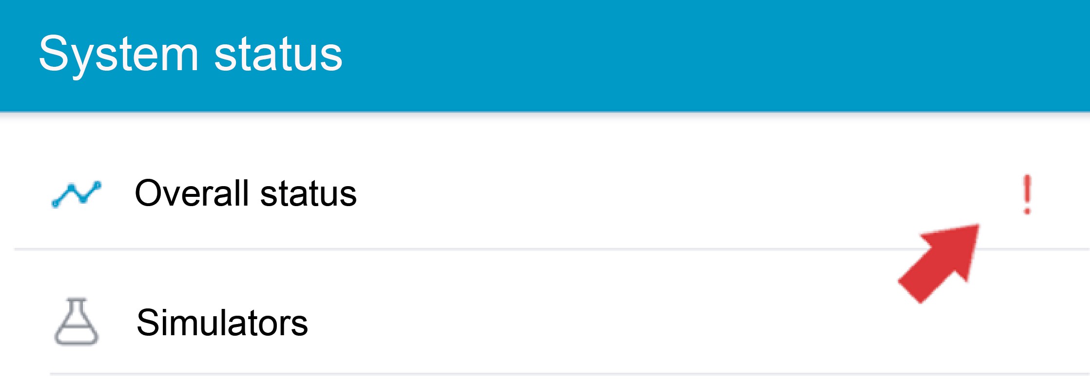
The system status can be checked after logging in at the top right using the color of the icon.
8.1.1. Fault display

|
System status: Everything is OK |

|
System status: Warning |

|
System status: Error (Fault) |
8.1.2. Troubleshooting
|
You can get a detailed overview of an existing warning or error by clicking on the exclamation mark in the top right-hand corner. |
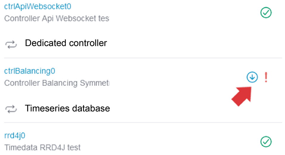
|
You can use the scroll bar to examine the origin of the warning or error in more detail. |
|
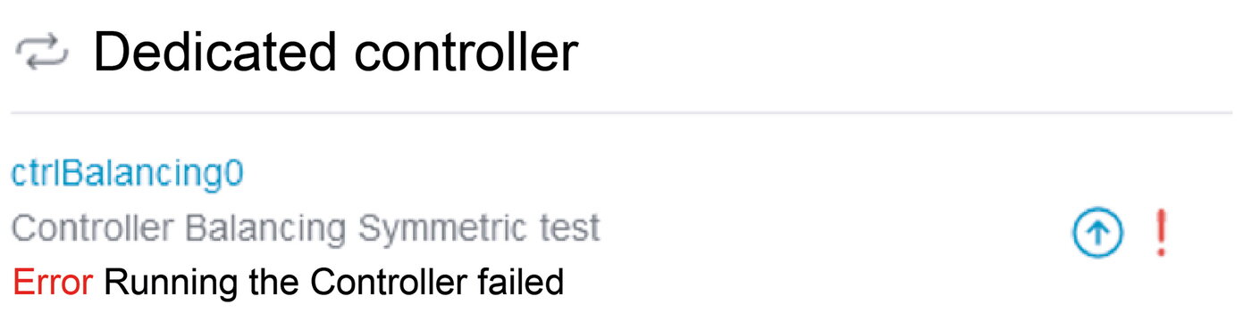
By clicking on the symbol (down arrow), a more detailed error description is displayed depending on the error. |
In the example above, an incorrect reference for the grid meter was intentionally entered for test purposes, which is why the controller execution fails.
The FENECON Service must be contacted to rectify errors.
|
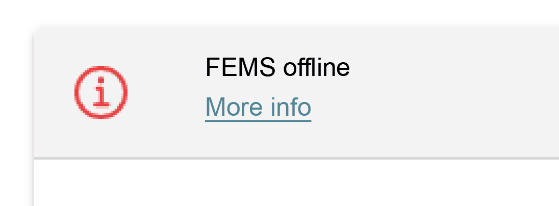
Under certain circumstances it can happen that the FEMS is not accessible and the adjacent error message appears. |
If the FEMS is offline, follow the steps displayed below the message.
8.2. FENECON Service
|
These installation and service instructions only contain work that can be carried out without specialist knowledge of the manufacturer. |
|
Work that is not described may only be carried out by authorized service personnel. Contact customer service to change parameters and programs. |
If the energy storage system malfunctions, contact the FENECON Service:
Phone: +49 (0) 9903 6280 0
E-mail: aftersales.industrial@fenecon.de
8.2.1. Details for the FENECON Service
The following information must be provided for the FENECON Service:
-
Device type/configuration.
-
FEMS number.
-
Serial number.
-
Currently installed software version.
-
Ticket number from previous faults (if available).
-
Inverter error code (if present).
The information can be found on the type label and in the system profile in Online Monitoring.
9. Technical maintenance
9.1. Tests and inspections
Residual risks:
|
When carrying out inspection work, ensure that the product is in a safe condition. Improperly performed inspections can have serious consequences for people, the environment and the product itself. |
|
Inspection work must only be carried out by trained and qualified specialists. |
|
The maintenance instructions for all individual components must be observed by authorized qualified electricians. |
Check the product and the cables regularly for visible external damage. If components are defective, contact the FENECON Service. Repairs must only be carried out by a qualified electrician.
9.2. Cleaning
|
Cleaning agents
|
9.3. Maintenance work
Residual risks:
|
During maintenance work, troubleshooting and assembly activities, ensure that the product is switched off in a safe manner and secured against being switched on again. Improperly performed maintenance and servicing activities can have serious consequences for people, the environment and the product itself. |
|
Before carrying out maintenance work on systems which could be under pressure or in which very hot/hazardous substances could still be present:
|
|
The product may only be serviced by persons who have received detailed instruction on the subject. |
|
The frequency of use and environmental conditions may make it necessary to vary the intervals between the activities described below.
|
|
Maintenance work must only be carried out by trained and qualified specialists. |
For maintenance of the inverters and the climate control unit, please refer to the documentation of the individual manufacturers and the FENECON maintenance instructions.
10. Storage
|
Storage longer than 6 months
This must only be carried out by the manufacturer or by a company commissioned by the manufacturer. |
-
Do not store the energy storage system with flammable or toxic objects.
-
Store energy storage systems with safety defects separately from undamaged ones.
-
The SoC of the individual slide-in battery modules of the energy storage system is ≥ 25 % SoC on delivery.
-
After 90 days, the SoC must be checked; this should be in the range of 15 to 35 % SoC. If this is not the case, charging or discharging must be carried out.
-
Recharging the slide-in battery modules is recommended from 20 % SoC.
Storage area: Fireproof indoors/outdoors with suitable weather protection
-
Air temperature: -20 °C to 40 °C.
-
Relative humidity: max. 50 % at +40 °C.
11. Utilization
The service life of the product depends on the service life and maintenance intervals carried out by specialist personnel. The service life is particularly influenced by preventive maintenance and servicing. Timely replacement of wearing parts and appropriate documentation of each activity is therefore crucial for the availability of the product.
All functional Safety elements must be replaced in good time before the calculated or specified service life in accordance with the number of operating cycles or operating time specified by the manufacturer. However, all functional Safety components should be completely overhauled after 20 years at the latest, in accordance with the applicable standard(s).
12. Transport (Fully-equipped variant)
This section contains information on external and internal transportation of the product.
Transportation is the movement of the product by manual or technical means.
-
Only use suitable and tested lifting gear and hoists for transportation!
-
The product must only be transported using the means of transport specified by the manufacturer.
Residual risks
|
||
|
||
|
||
|
Legal regulations
The off-site transportation of the product is carried out in accordance with the legal regulations of the country in which the product is transported off-site.
12.1. Safety instructions
-
Transportation is carried out by a hazardous goods carrier.
-
When transporting batteries, the current laws, regulations and standards must be observed (e. g. German Dangerous Goods Transportation Act (GGBefG)).
-
Upon receipt of the delivery, check it immediately for completeness and transport damage.
-
Use personal protective equipment (depending on the boundary conditions) (minimum requirement: protective headgear and protective footwear).
-
The electrical connections must be disconnected before transportation.
-
Before lifting, check that the attachment points and lifting gear are correctly seated.
-
The container should only be transported with a SoC of at least 25 %.
-
For correct transportation, follow the detailed lifting instructions (section: Assembly — Container).
-
The load capacity must be dimensioned so that the mass of the product can be safely absorbed (see section: [mass]).
-
The size of the transport surface must be dimensioned so that the product can be safely placed and secured on the transport surface.
12.2. Change of location
There are no plans to relocate the electrical energy storage facility after commissioning.
If a change of location is planned, FENECON GmbH must be consulted beforehand.
When changing location, the dismantled container can be transported using a suitable industrial truck or hoist.
The FENECON Industrial L, fully equipped with battery modules, has a weight of 11,000 kg.
12.3. Transport procedure
Means of transportation
A means of transport that meets the following requirements is needed for safe off-site transportation:
-
The load capacity must be dimensioned so that the mass of the product can be safely accommodated.
-
The size of the transport surface must be dimensioned so that the product can be placed safely on the transport surface without falling.
Required aids
The following aids are required for safe off-site transportation:
-
Loading and unloading: By means of forklift truck or crane.
-
Transportation: Only by motor vehicle for road transport.
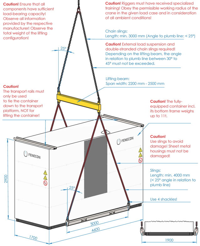
Lifting instructions
|
The electrical energy storage must only be transported fully loaded with a special lifting device, which does not remain with the customer and is the property of FENECON. |
-
A conveyor with a minimum load capacity of 11 tons is required to transport a fully loaded Industrial L (via forklift pockets).
-
For the correct lifting of a fully-equipped electrical energy storage, the information can be taken from the section [Unloading the container (fully-equipped)].
-
Information on weight, center of gravity and dimensions can be found in the sections Dimensions and Mass.
13. Dismantling and disposal
Residual risks:
|
||
|
13.1. Safety instructions
-
The following suitable personal protective equipment must be worn for all work:
-
Protective footwear.
-
Protective gloves, cut-resistant if necessary.
-
Protective eyewear.
-
-
The electrical energy storage system must only be dismantled by authorized qualified electricians.
-
Dismantling work must only be carried out when the system has been taken out of operation.
-
Before starting disassembly, all components to be removed must be secured against falling, tipping over or moving.
-
Dismantling work must only be carried out when the system is shut down and only by service personnel.
-
Use transport aids. Use existing attachment points for transporting the system parts.
-
The dismantling instructions of the component manufacturers (Appendix, Applicable documents) must be observed.
-
The slide-in battery modules are removed by service personnel and transported by hazardous goods transport.
-
When transporting the battery modules, the current laws, regulations and standards must be observed (e. g. Hazardous Goods Transportation Act — GGBefG).
13.2. Prerequisites
|
Sharp and pointed edges Injuries to the body or limbs caused by sharp and pointed edges on parts of the equipment.
|
-
The power supply to the storage system is interrupted and secured against being switched on again.
13.3. Waste disposal
|
After proper disassembly, the dismantled individual parts must be recycled:
-
The electrical energy storage system must not be disposed of with normal household waste.
-
Scrap metallic material residues.
-
Recycle plastic elements.
-
Dispose of the remaining components sorted according to material properties.
Electrical waste, electronic components, lubricants and other auxiliary materials are subject to hazardous waste treatment and may only be disposed of by authorized specialist companies.
Observe the following points when disposing of the electrical energy storage system or its components, as well as the operating and auxiliary materials:
-
Comply with local, national regulations.
-
Observe company-specific specifications.
-
Dispose of operating and auxiliary materials in accordance with the applicable safety data sheets.
-
Dispose of packaging material in an environmentally friendly manner.
Batteries
-
Do not expose the battery modules to high temperatures or direct sunlight.
-
Do not expose the battery modules to high humidity or corrosive atmospheres.
-
For special instructions on the disposal of used batteries, please contact the FENECON Service.
15. Register
15.1. Applicable documents
|
| No. | Component | Manufacturer documentation |
|---|---|---|
1 |
KACO blueplanet gridsave 92.0 kVa |
Available online: |
2 |
Envicool climate control unit |
Available online: |
3 |
EWON Cosy Router |
Available online: |